FEATURES
- Self Test Cable for Home Automation HAT for Raspberry Pi
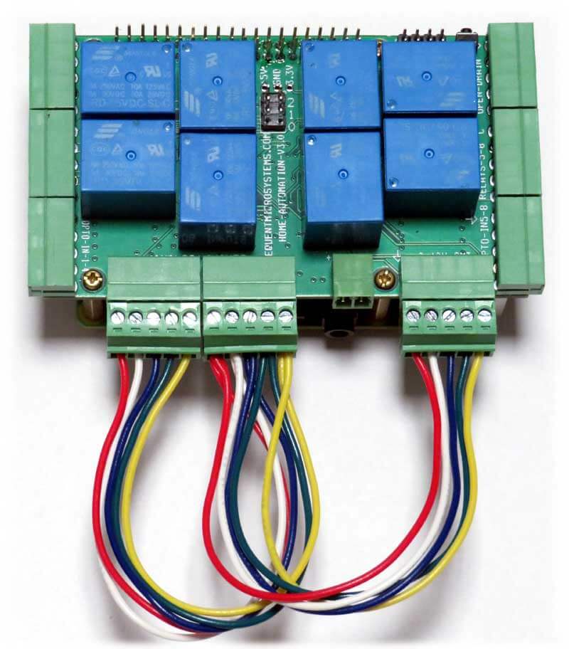
- Three-connector cable for self-testing the Home Automation card
- Self test groups of 2 inputs and outputs
- Command line software for each test
- Home Automation Self Test
DESCRIPTION
Raspberry Pi HOME AUTOMATION HAT
Versions 3.0 and up of the Home Automation HAT has been redesigned to use only pluggable connectors. Inputs and outputs are placed on the three sides of the card in groups of four. Each group has also a Ground or Common pin.
CARD LAYOUT

I/O PINOUT HANDY CARD
The Home Automation is accompanied by a Credit Card size, plastic laminated card which shows the I/O pinouts. Keep it handy. The back of the card shows the Raspberry Pi GPIO Connector pinout.

SELF TEST
Groups of three inputs and outputs can be self-tested with the help of this loopback cable.

1. TEST the GPIO and OPTO-INPUTS 1-4
Insert the cable on the left side of the card, as shown in the following picture, and run the self-test command
NOTE: This test is no longer available on the Version 4 of the Home Automation Card, where the upper left connector has been changed.

2. TEST the ANALOG INPUTS and OUTPUTS
Insert the cable on the bottom side of the card, as shown in the following picture, and run the self-test command.

3. TEST the OPEN DRAIN OUTPUTS and OPTO-INPUTS 5-8
Insert the cable on the right side of the card, as shown in the following picture, and run the self-test command.

4. TESTING THE RELAYS
Without the loopback cable, run the command relay_test. Relays will cycle on and off in sequence and the corresponding LED's will turn on and off.
LOOPBACK CABLE SCHEMATIC


