
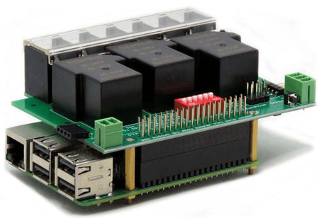
Three 40A-240V Relays RS485 Daisy-chainable HAT for Raspberry Pi
RS485 Daisy-channable through RS485 to 32 HATs; 40A/240VAC, 30VDC loads; DIN-Rail mountable.
Overview
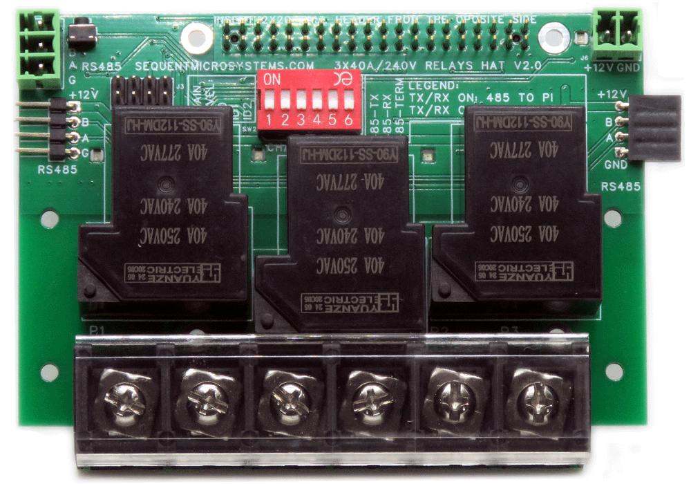
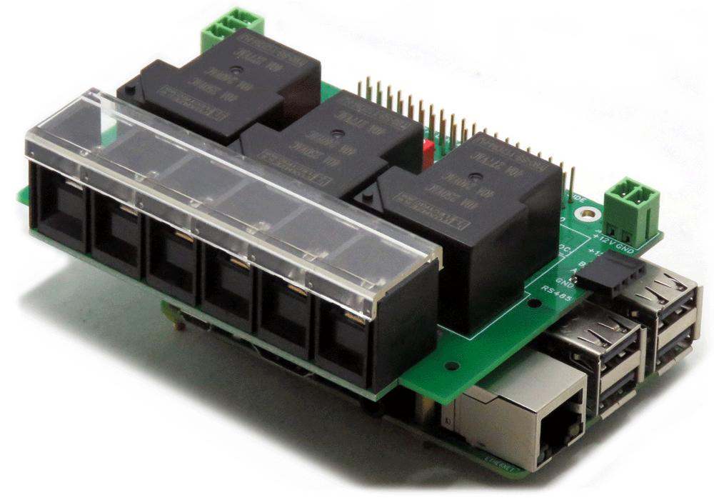
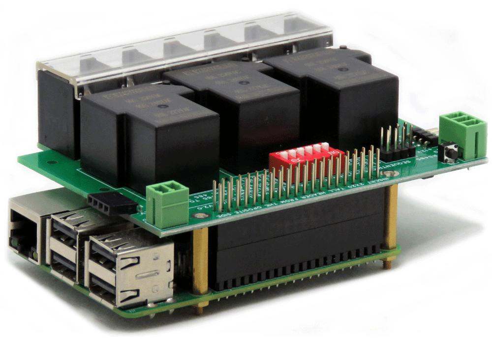
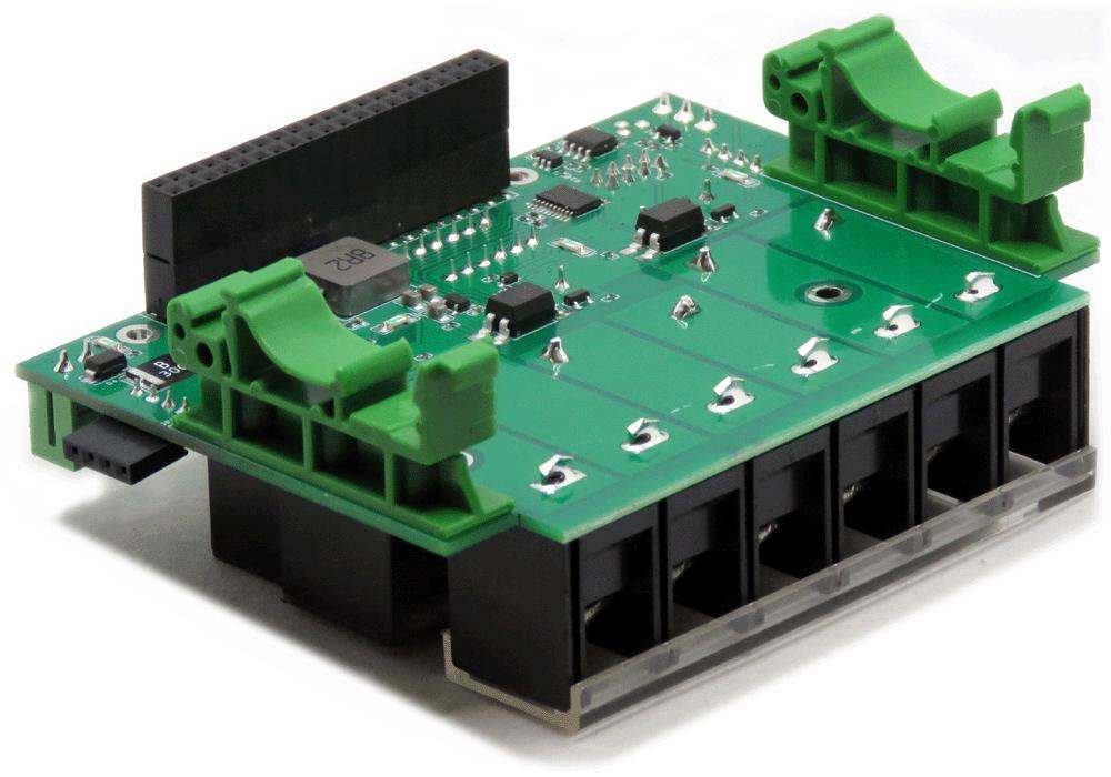
Compatible with all Raspberry Pi models from the Raspberry Pi Zero to Raspberry Pi 5, the Three 40A-240V Relays Card provides a compact and reliable solution for controlling high-power industrial loads such as three-phase heaters, motors, pumps, contactors, and lighting systems. Three heavy-duty relays, each rated for up to 40 A at 240 VAC, make the card suitable for demanding industrial automation applications.
When connected to a Raspberry Pi, the card communicates over the I²C interface and is supported by Command Line utilities, a Python library, and Node-RED nodes. It can also operate as a standalone MODBUS RTU slave over the RS485 interface, allowing direct control from any standard PLC, HMI, or SCADA system without requiring a Raspberry Pi.
- Three SPST-NO heavy duty relays, each rated 40A/277VAC inductive, 40A/30VDC
- RS485/MODBUS port with TVS protection and dual connectors
- Up to 8 cards stackable side-by-side on DIN Rail via I2C; up to 32 cards via RS485
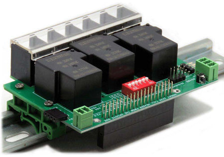
- DIN-Rail mounting hardware included
- Uses only I2C port — all GPIO pins remain free
- Works with any Raspberry Pi from Zero to 5
- ECCN classification EAR99 — freely exportable under U.S. regulations.
- Ambient operating temperature: -40°C to 85°C
Software Integration
Write your application using the Command Line or Python library, or use Node-RED for visual flow-based programming with no code required.
 |
 |
 |
INTERFACES AND I/O
| I/O's | Communication | Software Integration |
|---|---|---|
| • Three SPST-NO Heavy Duty Relays (40A/277VAC) | • I2C Port to Raspberry Pi | • Command Line |
| • RS485/MODBUS Port | • Python Library | |
| • Node-RED nodes | ||
| Other Features | ||
| • LED indicator on each relay; power LED shows when power is applied | ||
| • General purpose push-button routed to GPIO 26 (pin 37) | ||
| • RS485 TVS protection, dual connectors | ||
| • 12V power supply; provides 5V/5A to Raspberry Pi | • Heavy-duty 40A/750V terminal block; pluggable connectors 26–16 AWG | |
| • On-board resettable fuse | • 8 cards stackable side-by-side on DIN Rail via 4-pin side header | |
DESCRIPTION
The Three 40A-240V Relays card provides everything needed to control heavy-duty industrial loads with Raspberry Pi — or stand-alone on a DIN Rail as a MODBUS RTU slave.
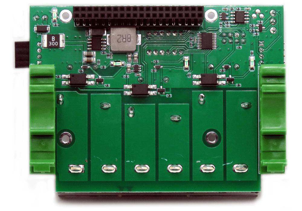
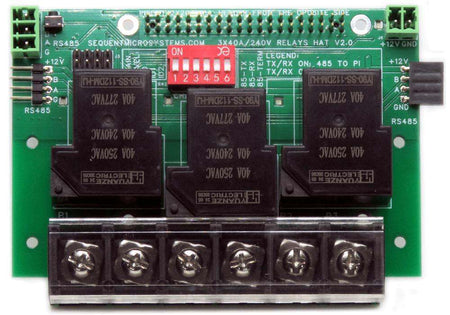
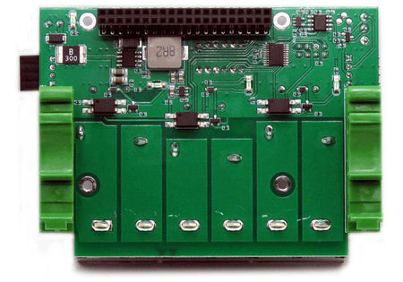
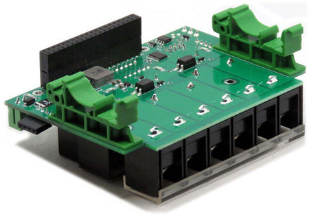
Three SPST-NO contacts rated 40A/277VAC inductive, 40A/VAC resistive, and 40A/30VDC. Heavy-duty 40A/750V terminal blocks accept large-gauge wire for direct connection to high-current loads.
The on-board RS485 transceiver with TVS protection and dual connectors operates in two modes: controlled by the Raspberry Pi over I2C, or as a standalone MODBUS RTU slave where any PLC, SCADA, or HMI can control all relays — no Raspberry Pi required. Up to 32 cards can be chained on a single RS485 bus.
Each relay has a dedicated LED indicator that lights when the relay is energized, giving immediate visual feedback of relay state. A power LED shows when the card is powered.
A momentary push-button at the edge of the card is routed to GPIO 26 (pin 37). It provides a convenient way to safely shut down the Raspberry Pi without a keyboard or monitor — write a script to monitor the pin and issue the shutdown command when pressed. The button can also be used for any other custom task such as toggling relays.
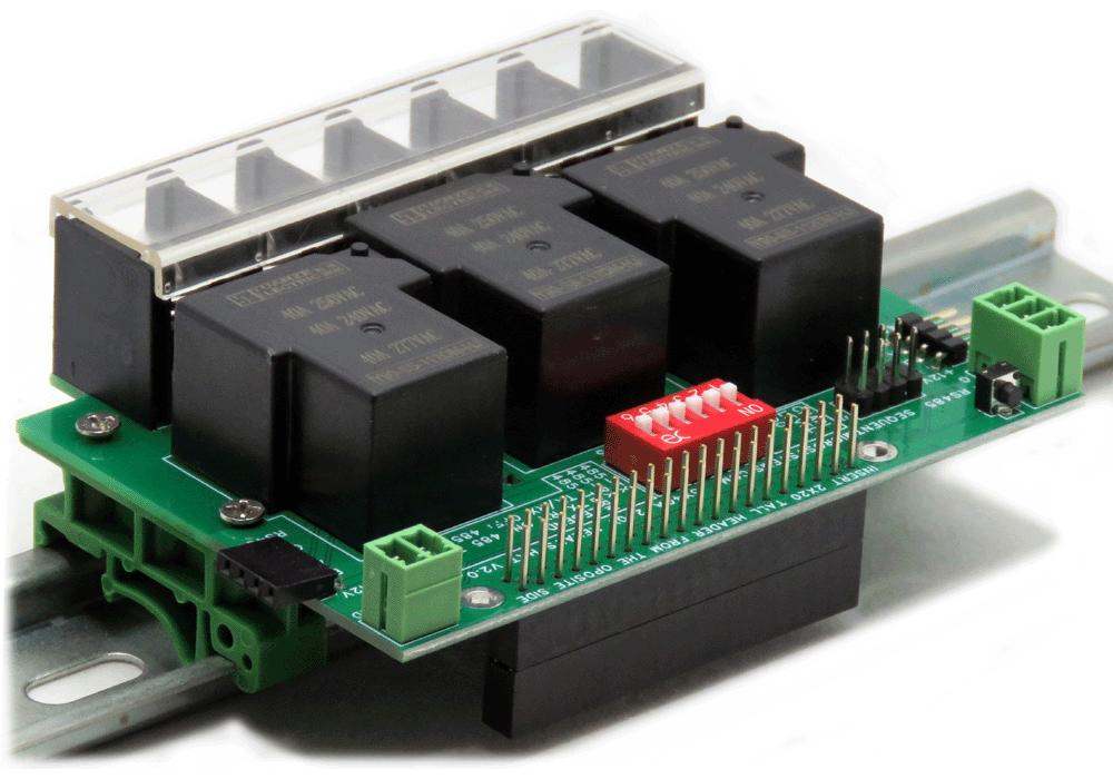
The card mounts on a standard DIN Rail using the included brackets. Multiple cards connect side-by-side on the DIN Rail via a 4-pin male-female side header, sharing the I2C bus without any external wiring or cables.

A single CLI command runs a self-test before installation: each relay cycles on and off at 0.3-second intervals. The relay clack and LED changes confirm that all three relays are functioning correctly.
TECHNICAL DETAILS
CARD LAYOUT

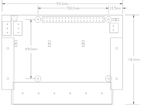
MECHANICAL SPECIFICATIONS
DIP SWITCH AND STACKING
The onboard six-position DIP switch configures the stack address and the RS485 port behavior. Multiple cards connect side-by-side on a DIN Rail via the 4-pin side header, sharing the I2C bus. Up to 8 cards can be addressed independently using the ID bits.
| Switch | Name | Function |
|---|---|---|
| ID0 | Stack ID bit 0 | Binary stack address bit 0 (LSB) — sets card address 0–7 |
| ID1 | Stack ID bit 1 | Binary stack address bit 1 |
| ID2 | Stack ID bit 2 | Binary stack address bit 2 (MSB) |
| RX | RS485 RX select | ON: Raspberry Pi receives RS485 directly |
| TX | RS485 TX select | ON: Raspberry Pi drives RS485 directly |
| TERM | RS485 termination | Enable on the last card in an RS485 chain to prevent signal reflections |
ELECTRICAL SPECIFICATIONS
| Power | |
|---|---|
| Power supply | 12 VDC, pluggable connector |
| Power to Raspberry Pi | 5V / 5A |
| Quiescent current | 10 mA (all relays off) |
| Relay coil current | 80 mA per relay |
| Onboard resettable fuse | Yes |
| Relay Contacts | |
|---|---|
| Contact configuration | SPST-NO |
| Rated current | 40 A |
| Max AC voltage | 277 VAC (inductive load) |
| Max DC voltage | 30 VDC |
| On/off time | 20 ms max each |
| Electrical endurance | 600 cycles/hour at full load |
| Mechanical endurance | 18,000 cycles/hour (no load) |
| Electrical life | 50,000 operations min at 40A/277VAC |
| Mechanical life | 10,000,000 operations min (no load) |
POWER REQUIREMENTS
Power supply: The card requires a 12VDC power supply connected to its pluggable power connector. It supplies 5V and up to 5A to the Raspberry Pi over the GPIO bus, eliminating the need for a separate Raspberry Pi power supply. The relay coils are powered from the 12V supply; each relay draws 80mA when energized. The card itself draws only 10mA when all relays are off.
PLUGGABLE CONNECTORS
All signal connections use pluggable screw terminal connectors accepting wire gauges from 26 to 16 AWG. Relay output contacts connect to heavy-duty 40A/750V terminal blocks. Connectors can be unplugged from the board for convenient field wiring without disturbing the rest of the installation.
COMMUNICATION INTERFACES
FIRMWARE UPDATE
The onboard microcontroller firmware can be updated in the field. The update tool downloads the latest firmware from Sequent Microsystems' servers and flashes it to the board over I2C.
Running the Update
~$ cd ~/3relind-rpi/update/
~/3relind-rpi/update$ ./update <id>
Replace <id> with the board stack address (0-7). Full instructions including recovery procedures are available at:
https://github.com/SequentMicrosystems/3relind-rpi/tree/main/update/README.md
COMPATIBILITY
| Interface | I2C |
| GPIO used | GPIO2 (SDA), GPIO3 (SCL) — 2 pins only; remaining GPIO pins stay free |
| Max I2C stack | 8 cards side-by-side on DIN Rail via 4-pin side header |
| Max RS485 chain | 32 cards (standalone, no Raspberry Pi required) |
| Compatible with | All Raspberry Pi versions from Zero to 5 (40-pin GPIO header) |
DOWNLOADS
| User's Guide | Schematics (PDF) | CAD | Software & Integrations |
|---|---|---|---|
| User's Guide | Schematic V1.0 | 3D STEP Model V1.1 | Command Line |
| 2D CAD Drawing | Python Library | ||
| Node-RED Nodes | |||
| Node-RED Examples | |||
| Relays Datasheet |
COMPLIANCE
RoHS and REACH Compliance Declaration
WHAT'S INCLUDED
When you purchase the card you will receive the following items:
| 1. Three 40A-240V Relays Card for Raspberry Pi |
|---|
 |
| 2. Mounting Hardware | |
|---|---|
 |
|
| 3. Connector Plugs | |
|---|---|
 |
Pluggable connector plugs for all card connections including RS485 port and power. |
| 4. DIN-Rail Mounting Brackets and Screws | |
|---|---|
 |
Two DIN-Rail mounting brackets with screws for installing the card on a standard DIN Rail without a Raspberry Pi. |
QUICK START
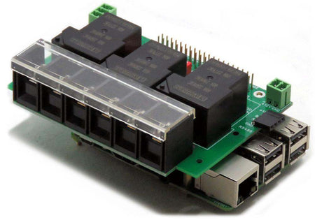
- Plug your card on top of your Raspberry Pi and power up the system.
- Enable I2C communication on Raspberry Pi using
raspi-config. - Install the software from GitHub:
~$ git clone https://github.com/SequentMicrosystems/3relind-rpi.git~$ cd /home/pi/3relind-rpi~/3relind-rpi$ sudo make install~/3relind-rpi$ 3relind
The program will respond with a list of available commands. To read more about the CLI, please refer to the README file. If you would rather use a different platform, you can access the same functionality through dedicated, ready-to-use integrations in the Downloads tab above.
Expand Your System
-
 In stock
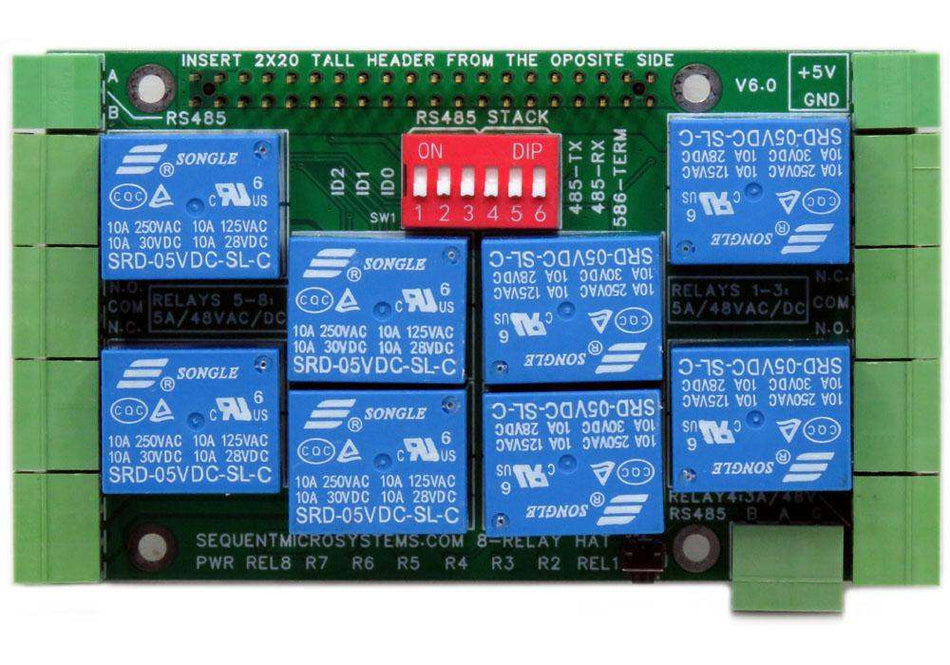
Eight Relays 4A/120V 8-Layer Stackable HAT for Raspberry Pi
Eight Relays 4A/120VAC, 24VDC N.O./N.C. contacts and LED indicators; RS485 Port. -
 In stock
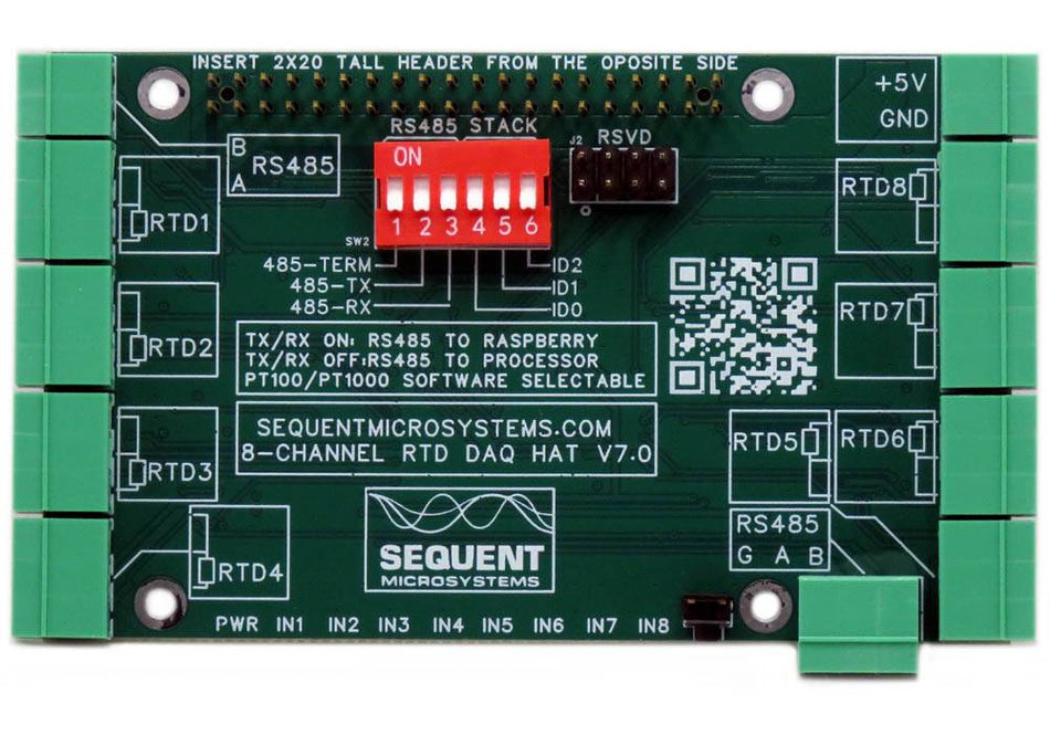
RTD Data Acquisition 8-Layer Stackable HAT for Raspberry Pi
Eight Channel RTD Data Aquisition HAT; 0.01% accuracy through calibration; PT100/1000 Sensors; RS485/MODBUS, Watchdog. -
 In stock
Sixteen LV Digital Inputs 8-Layer Stackable HAT for Raspberry Pi
Sixteen 3V-24V Opto-isolated Inputs with LED indicators; RS485/MODBUS, Hardware Watchdog. -
 In stock
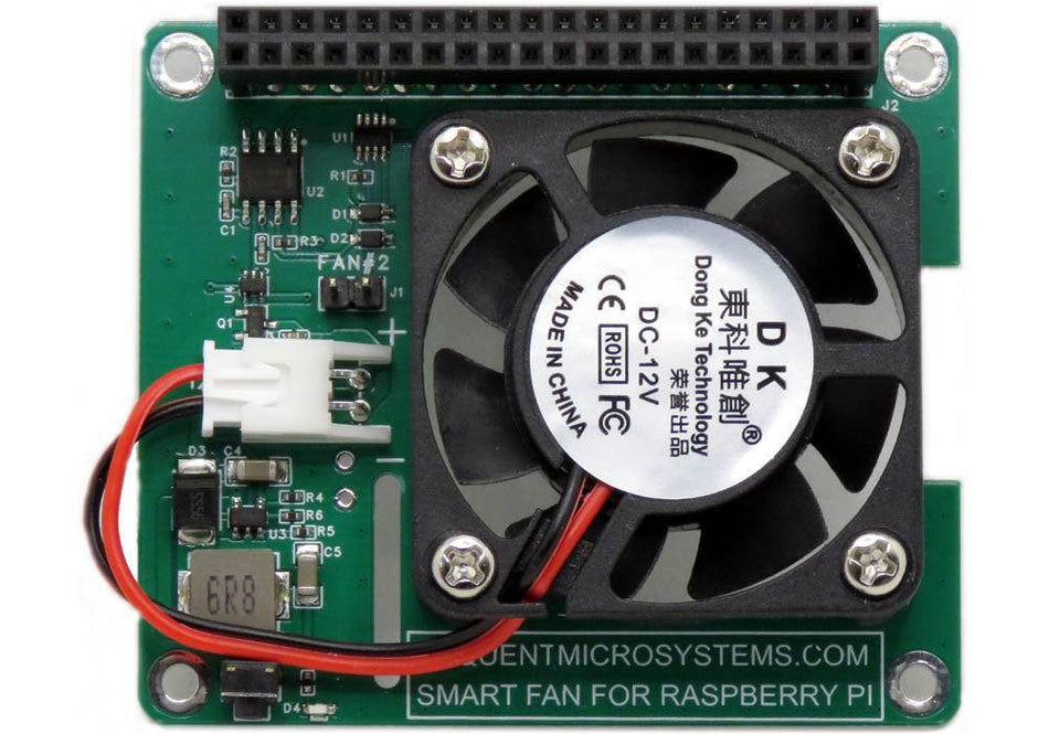
Smart Fan HAT the Best Cooling Solution for Raspberry Pi
PWM controlled 40x40x10mm Fan keeps Raspberry Pi temperature constant; Stackable with any other HAT.
