


16-Channel HV-SS Relay Card for Raspberry Pi Back Panel
16-channel relay card for Raspberry Pi Back Panel: 8 low power and 8 solid state relays
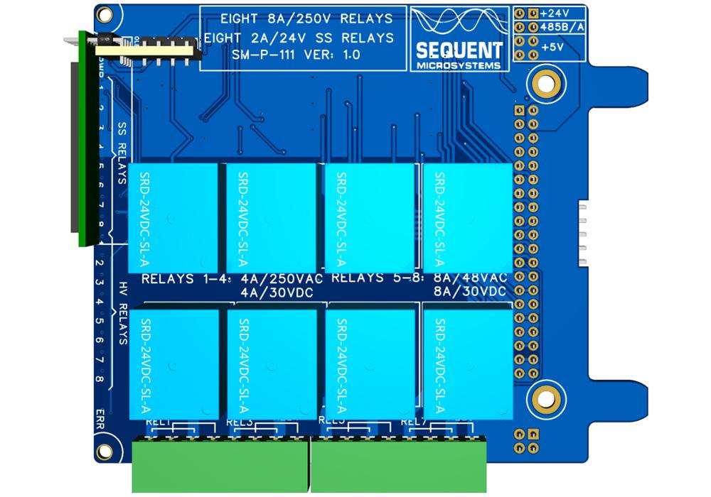
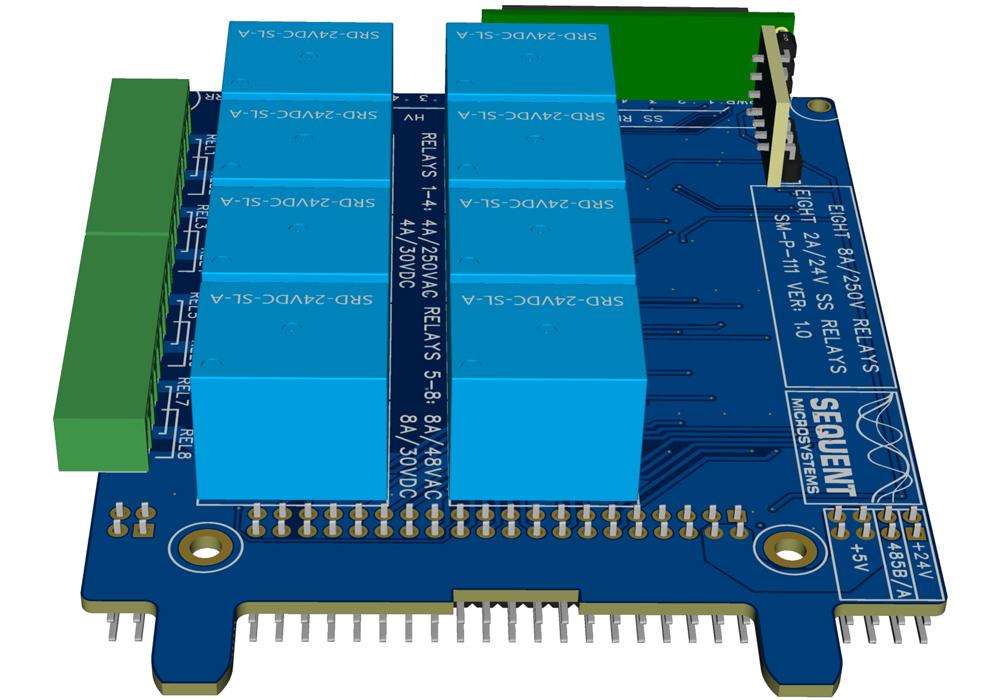
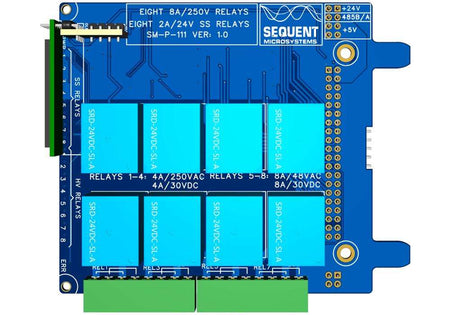
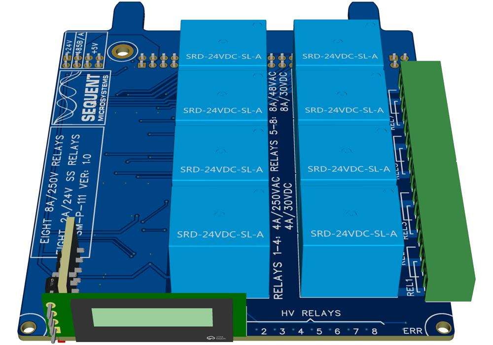
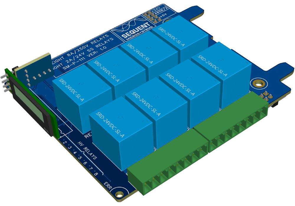
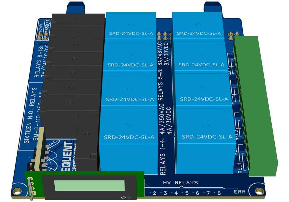
The 16-Channel HV-SS Relay Card adds sixteen relays to your Raspberry Pi Back Panel, giving you flexible control over a wide range of loads. It combines four relays rated for 250 VAC/4A, four relays rated for 48 VAC/8A, and eight solid state-relays rated for 24 VAC/DC/2 A, making it suitable for everything from light automation tasks to fast-power switching. Designed for reliability and ease of use, it is an ideal choice for industrial control, home automation, and custom electronics projects.
Seamlessly integrated with the Raspberry Pi Back Panel, the card supports Command Line, MODBUS RTU over RS485, CAN support via CANopen, OpenPLC, and CODESYS.
FEATURES
- Plugs directly into the Raspberry Pi Back Panel - no additional wiring or hardware needed
- 16 onboard relays:
- 4 x 250V / 4A (high voltage)
- 4 x 48VAC / 8A (high current)
- 8 x 24VAC/DC / 2A (solid-state)
- Dedicated connectors:
- High/medium-power relays routed through 2×8-pin pluggable connectors
- Solid-state relays wired directly to the Back Panel for easy integration
-
Seamless compatibility with Raspberry Pi Back Panel and other HOP cards
- LED indicators on all relays
- Mix of high- and low-power switching in a single expansion card
- Reliable isolation for safe operation across different loads
- Compact design optimized for Back Panel slots
- Convenient wiring with pluggable terminals for higher loads
- ECCN classification: EAR99
- Open source hardware - schematics available
DESCRIPTION
Part of the HOP (Hardware On Panel) family developed by Sequent Microsystems, the 16-Channel HV-SS Relay Card is designed to integrate seamlessly with the Raspberry Pi Back Panel. Up to eight HOP cards—of any type—can be installed on a single Back Panel, offering maximum flexibility for industrial automation applications. Multiple Back Panels can be connected horizontally to support larger projects.
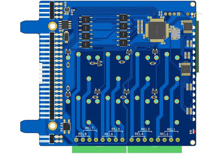
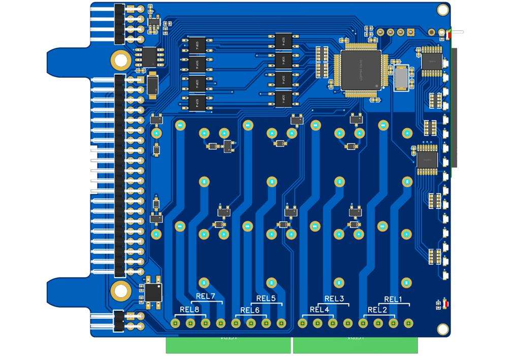
Eight solid-state relays are routed to the Back Panel through the J1 2x20 pin connector and can be accessed on the spring loaded connectors. Loads are limited to 2A and 24VAC or DC.
Four high power relays are routed to J2 8-pin connector and can drive loads of up to 250VAC or 30VDC and 4A.
Four medium power relays are routed to J3 8-pin connector and can drive loads of up to 48VAC or 30VDC and 8A.
All contacts are N.O.

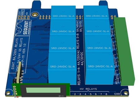
Like all HOP cards, the 16-Channel HV-SS Relay Card features 18 LED indicators. The power LED blinks when power is applied and the local processor is operational. An error LED illuminates when the dedicated PANIC pin on the Back Panel terminal block is activated. Sixteen LEDs show the status of the relays.
An RS485 port enables communication with external PLCs or industrial controllers using the industry-standard MODBUS RTU protocol.
Power Requirements
The card is powered via the Back Panel power connector. All the relay coils use 24VDC. The solid-state relays need 2.5 mA each to operate. The medium and high power relays require 15mA each. The local processor is powered from the 5V rail through a 3.3V LDO regulator and consumes 10 mA.


-
Power Supply: 5V 10mA;
- Solid-state relays: 8×2.5 mA = 20 mA
- Med/high coils: 8×15 mA = 120 mA
- Max all on ≈ 200 mA (+ logic 10 mA @ 5 V).

DOWNLOADS
Hardware Schematic V1.0
2D DXF Mechanical
3D STEP Model
3D Printable Enclosure
SOFTWARE
Command Line Drivers
Python Libraries
CODESYS Driver
OpenPLC Module
QUICK START
- Plug the card on the Back Panel for Raspberry Pi and power up the system.
- Enable I2C communication on Raspberry Pi using raspi-config.
- Install the software from github.com:
- git clone https://github.com/SequentMicrosystems/sequent-cli.git
- cd /home/pi/sequent-cli
- sudo make install
- sequent-cli 8ssrel -h
FAQ
Q: How is the stack position determined?
A: Automatically, by the physical slot on the Back Panel—no DIP switches or software setup needed. The slot is also shown on the OLED at power-up.
Q: Which relays go to the Back Panel vs. pluggable connectors?
A: The eight solid-state relays (24 V/2 A) route to the Back Panel spring terminals via the J1 2×20; the four 250 V/4 A relays go to J2 (2×8), and the four 48 V/8 A relays go to J3 (2×8). All contacts are N.O.
Q: Can I control the card without a Raspberry Pi?
A: Yes. Over RS485, the card acts as a MODBUS RTU slave and can be driven by any MODBUS-compatible PLC/controller.
Q: How is RS485 wired and managed?
A: The RS485 port is permanently tied into the Back Panel’s shared RS485 bus and handled by the on-board processor for MODBUS RTU communication.
Q: What happens if the Raspberry Pi hangs?
A: With Watchdog enabled, the card signals the Back Panel to hard-reset the Pi (power off ~10 s) if the Pi stops responding in time.
Q: How many cards can I use?
A: Up to eight HOP cards (any mix) per Back Panel; multiple Back Panels can be chained horizontally for larger systems.
Q: Any best practices for switching inductive loads (motors, solenoids)?
A: Use proper snubbers (RC for AC, flyback/suppressors for DC) and external fusing appropriate to the load to reduce arcing and extend relay life. (General guidance; choose values per your load.)
Q: Where can I find documentation and examples?
A: Visit Sequent Microsystems’ GitHub repository for open-source code, wiring diagrams, and setup instructions:
👉 https://github.com/SequentMicrosystems
Related products
-
 Coming soon
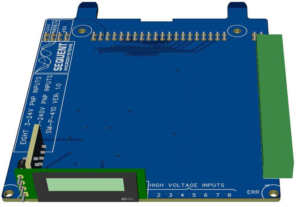
16-Channel Digital Inputs HV/LV for Raspberry Pi Back Panel
8 High Voltage and 8 Low Voltage optoisolated PNP inputs for Sequent Microsystems Back Panel -
 Coming soon
16-Channel HV-LV Relay Card for Raspberry Pi Back Panel
16-channel relay card for Raspberry Pi Back Panel: 8 low power and 8 high power relays -
 Coming soon
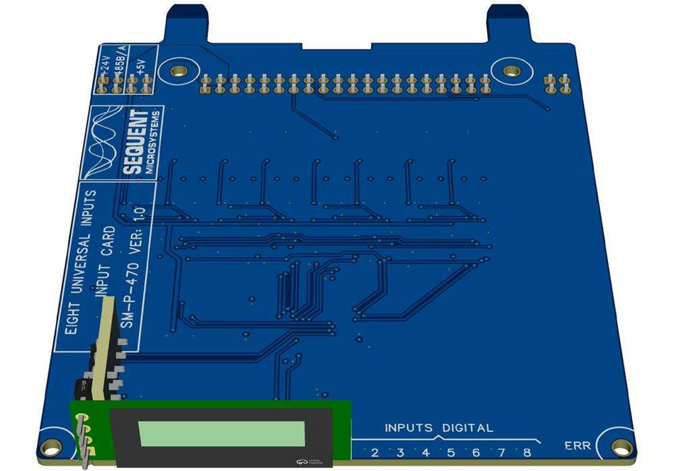
16-Channel Universal Input Card for Raspberry Pi Back Panel
8-Channel Universal Input Card: 0-3.3V, 0-10V, 4-20mA, 1K/10K Thermistors, Dry Contact/Counters -
 Coming soon
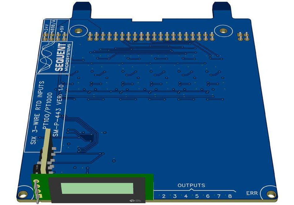
6-Channel 3-wire RTD Card PT100 and PT1000 for Raspberry Pi Back Panel
Six channel RTD Card with Software Selectable PT100 or PT1000 probes


