


Building Automation 8-Layer Stackable HAT for Raspberry Pi
Eight universal inputs: 1K/10K Thermistors, 0-10V, Dry Contact; Four 24VAC outputs; Four 0-10V outputs; 1-Wire, RS485, RTC, Watchdog.
Overview
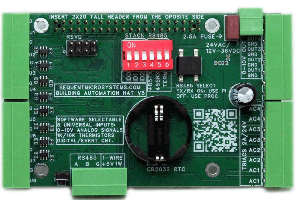
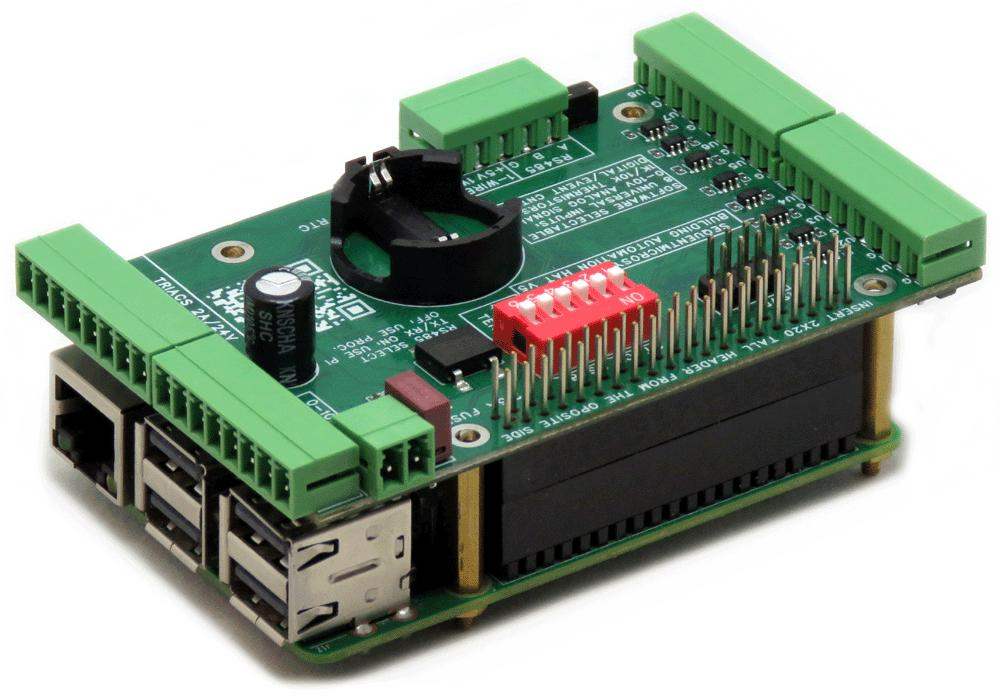
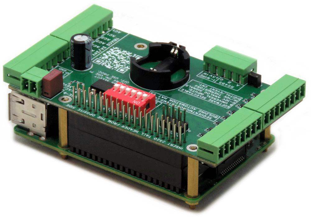
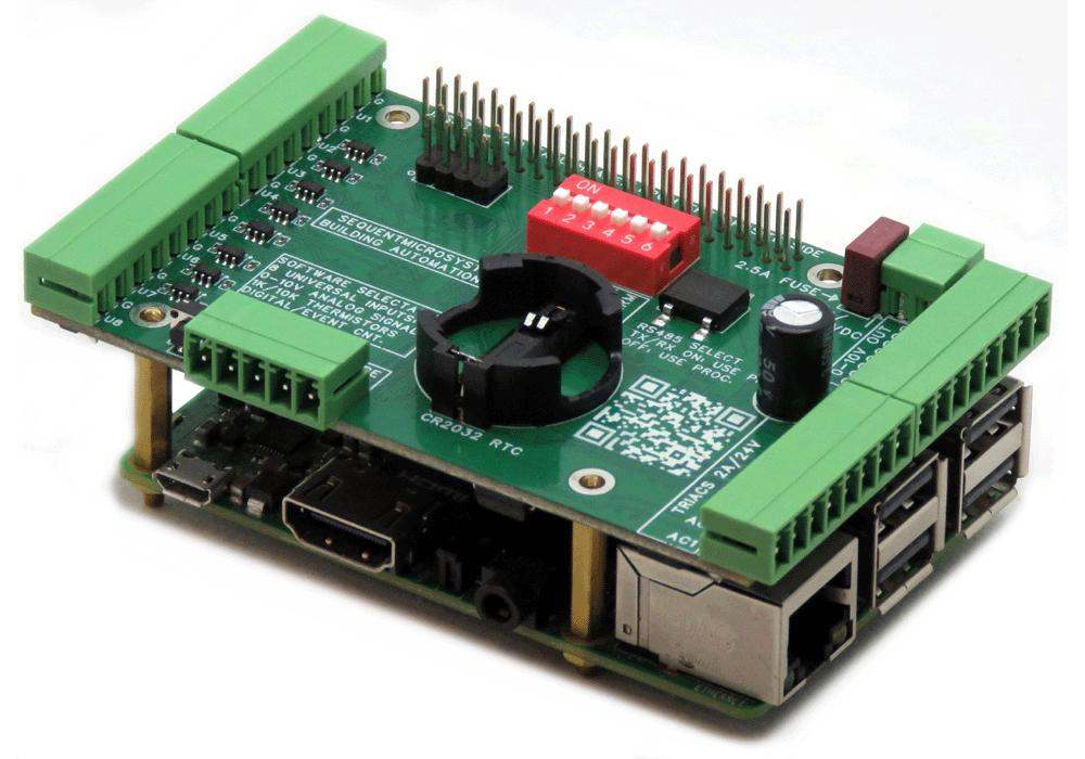
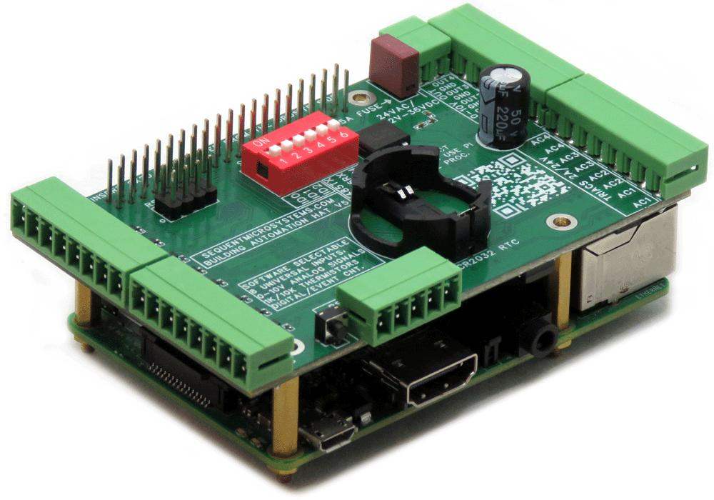
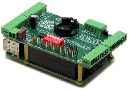
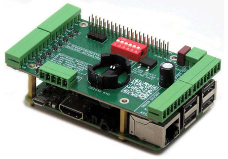
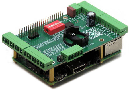
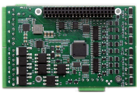
Building automation hardware for Raspberry Pi with software-selectable universal inputs, standard communication interfaces, and support for widely used control and monitoring systems. The Building Automation HAT combines universal analog and sensor inputs, TRIAC and 0-10V outputs, RS485/MODBUS, and 1-Wire interfaces in a compact, stackable platform for HVAC, lighting, and building management applications.
- Eight software-selectable universal inputs: 0-10V, 1K/10K thermistors, or dry contact
- Native RS485 / MODBUS and 1-Wire interfaces
- Four TRIAC outputs for 24VAC load control and four 0-10V outputs for dimming
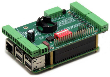
- Up to 8 cards of each type can be stacked and mixed with other Sequent HATs for virtually unlimited I/O expansion
- Designed for HVAC, lighting control, and building management systems
- CE Certified
Works with Open Automation Software
Compatible with widely used tools for control, monitoring, and system integration.
 |
 |
 |
 |
 |
 |
 |
INTERFACES AND I/O
| I/O's | Communication | Software Integration |
|---|---|---|
| • Eight Universal Inputs: | • I2C Port to Raspberry Pi | • Command line |
| • 1K or 10K thermistors | • RS485/MODBUS Port | • Python Library |
| • 0-10V analog inputs | • 1-Wire Interface | • Node-RED nodes |
| • Dry contact/counter inputs | • CODESYS Driver | |
| • Four AC TRIAC Outputs, 1A/24VAC | • OpenPLC Module | |
| • Four 0-10V Outputs | • Home Assistant | |
| • Four General Purpose LEDs | • Arduino | |
| Other Features | ||
| • Software-selectable universal input configuration | ||
| • Wide range 12-36VDC or 24VAC power supply delivers 5V to Raspberry Pi | ||
| • 500Hz sample rate on 0-10V inputs | • Status LEDs on all Digital Inputs and Outputs | |
| • Works with any Raspberry Pi from ZERO to 5 | • Pluggable Connectors 26-16 AWG wires | |
| • TVS Protection on all Inputs | • On Board Hardware Watchdog and fuse | |
| • Real Time Clock With CR2032 Battery Backup | • Eight Level Stackable | |
DESCRIPTION
The Building Automation HAT provides everything needed to build HVAC, lighting, and building management systems with Raspberry Pi.
Eight universal inputs are software-selectable per channel — configure each one independently as a 0-10V analog input, a 1K or 10K thermistor, or a dry contact/counter input with no jumpers or DIP switches required.
Four AC TRIAC outputs switch 24VAC loads up to 1A for direct control of fans, dampers, and valves.
Four 0-10V outputs provide proportional control of light dimmers, variable-speed drives, and other analog actuators.
Connect to other building automation systems using the RS485/MODBUS port. Read up to 16 DS18B20 temperature sensors via the 1-Wire interface.
Four general purpose LED outputs display the state of any digital or analog channel.
The Real-Time Clock with CR2032 battery backup keeps accurate time through power failures, making the card ideal for scheduled control and time-stamped event logging.
The hardware watchdog automatically power-cycles the Raspberry Pi if the software becomes unresponsive, ensuring continuous operation in unattended deployments.
TVS diodes on all inputs protect against ESD and transient spikes. An onboard resettable fuse protects against accidental shorts.
The card communicates over I2C using only two of the Raspberry Pi's GPIO pins, leaving the remaining 24 GPIOs free for user applications. Compatible with all Raspberry Pi versions from Zero to 5. Up to 8 cards of each type can be stacked on a single Raspberry Pi, and cards of different types can be freely mixed in the same stack. Three DIP switch positions (ID0, ID1, ID2) set each card's stack address.
TECHNICAL DETAILS
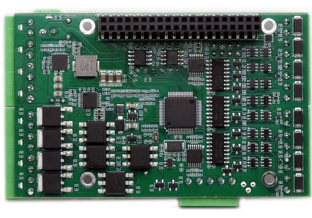
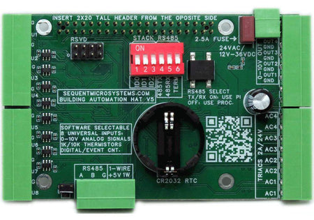
CARD LAYOUT

MECHANICAL SPECIFICATIONS

DIP SWITCH AND STACKING
The onboard six-position DIP switch configures both the stack address and the RS485 port behavior. Cards of different Sequent HAT types can be freely mixed in the same stack.
| Switch | Name | Function |
|---|---|---|
| ID0 | Stack ID bit 0 | Binary stack address bit 0 (LSB) — sets card level 0–7 |
| ID1 | Stack ID bit 1 | Binary stack address bit 1 |
| ID2 | Stack ID bit 2 | Binary stack address bit 2 (MSB) |
| RX | RS485 RX select | ON: Raspberry Pi receives RS485 directly |
| TX | RS485 TX select | ON: Raspberry Pi drives RS485 directly |
| TERM | RS485 termination | Enable on the last card in an RS485 chain to prevent signal reflections |
ELECTRICAL SPECIFICATIONS
| Power | |
|---|---|
| Power supply | 3.5mm Pluggable Connector, 12–36VDC or 24VAC |
| Power consumption | 50 mA @ 24 V |
| Onboard resettable fuse | 1 A |
| 0–10 V Inputs | |
|---|---|
| Maximum Input Voltage | 12 V |
| Input Impedance | 20 KΩ |
| Resolution | 12 bits |
| Sample rate | 500 sps |
| Full scale linearity | 0.15% |
| Contact Closure Inputs | |
|---|---|
| Maximum frequency | 100 Hz |
| 0–10 V Outputs | |
|---|---|
| Minimum Output Load | 1 KΩ |
| Resolution | 0.1% |
| Full scale linearity | 0.1% |
| Triac Outputs | |
|---|---|
| Maximum Output Current | 1 A |
| Output Voltage | 24 VAC |
POWER REQUIREMENTS
Power supply: The card requires an external 12–36VDC or 24VAC power supply connected to its own pluggable power connector. The card supplies 5V and up to 4A continuous, 5A peak to the Raspberry Pi over the GPIO bus, eliminating the need for a separate Raspberry Pi power supply. Operating current is 50mA at 24V.
PLUGGABLE CONNECTORS
All I/Os connect to heavy-duty 3.5mm pitch pluggable screw terminal connectors rated at 8A, accepting wire gauges from 26 to 16 AWG. Connectors can be unplugged from the board for convenient field wiring and debugging without disturbing the rest of the installation.
SELECTING THE UNIVERSAL INPUTS
The default setting of the Universal Inputs is 0-10V. In order to change it:
- Make sure you have the latest software installed, instructions in the readme.
- Run the command "megabas 0 incfgwr <channel> <value>", where:
- channel = 1-8
- value = 0 for 0-10V, 1 for 1K Thermistor, 2 for 10K Thermistor
- value = 3 for Dry contact/Counter
For more info on the commands type "megabas -h incfgwr" and "megabas -h incfgrd"
FIELD CALIBRATION
All analog inputs and outputs are factory-calibrated. However, firmware commands allow the user to recalibrate the board or perform higher-precision calibration if required.
Calibration is performed using a two-point method. The selected calibration points should be placed as close as possible to the minimum and maximum values of the measurement range.
Input Calibration
To calibrate the inputs, the user must apply known analog reference signals. For example, calibrating the 0-10V inputs requires an adjustable 0-10V power supply; calibrating the thermistor inputs requires known precision resistors placed at the two ends of the measurement range.
Output Calibration
To calibrate the outputs, the user must:
- Issue a command to set the output to a desired value.
- Measure the actual output using a calibrated instrument.
- Issue the corresponding calibration command to store the measured value.
Storage and Reset
Calibration values are stored in non-volatile flash memory, and the input transfer curve is assumed to be linear.
If an incorrect command or value is entered during calibration, a RESET command can restore the selected channel to its factory calibration values. After a reset, the calibration procedure can be repeated.
The following firmware commands are available for performing calibration:
CALIBRATE 0-10V INPUTS:                    megabas <id> adccal <channel> <value>
RESET CALIBRATION OF 0-10V INPUTS:         megabas <id> adccalrst <channel>
CALIBRATE 1K THERMISTOR INPUTS:            megabas <id> r1kcal <channel> <value>
RESET CALIBRATION OF 1K THERMISTOR INPUTS: megabas <id> r1kcalrst <channel>
CALIBRATE 10K THERMISTOR INPUTS:           megabas <id> r10kcal <channel> <value>
RESET CALIBRATION OF 10K THERMISTOR INPUTS: megabas <id> r10kcalrst <channel>
CALIBRATE 0-10V OUTPUTS:                   megabas <id> daccal <channel> <value>
RESET CALIBRATION OF 0-10V OUTPUTS:        megabas <id> daccalrst <channel>
COMMUNICATION INTERFACES
HARDWARE WATCHDOG
The Building Automation HAT includes a hardware watchdog that ensures your system automatically recovers if the Raspberry Pi software becomes unresponsive. The watchdog is disabled at power-up and activates after it receives the first reset command from the Raspberry Pi.
| Watchdog Parameters | |
|---|---|
| Default timeout | 120 seconds |
| Initial timeout period | Configurable — allows time for Raspberry Pi to boot and start the application |
| Running timeout period | Configurable — normal operating timeout |
| Off period | 10 seconds before power is restored |
| Reset counter | Stored in non-volatile flash; can be read or cleared at any time |
For a full list of watchdog commands, run: megabas -h
COMPATIBILITY
| Interface | I2C |
| GPIO used | GPIO2 (SDA), GPIO3 (SCL) — 2 pins only; remaining 24 GPIO pins stay free |
| Max stack | 8 cards of each type; different Sequent HATs can be freely mixed with virtually no upper limit on total I/O |
| Compatible with | All Raspberry Pi versions from Zero to 5 (40-pin GPIO header) |
FIRMWARE UPDATE
The onboard microcontroller firmware can be updated in the field. The update tool downloads the latest firmware from Sequent Microsystems' servers and flashes it to the board over I2C.
Running the Update
~$ cd ~/megabas-rpi/update/
~/megabas-rpi/update$ ./update <id>
Replace <id> with the board stack address (0-7). Full instructions including recovery procedures are available at:
https://github.com/SequentMicrosystems/megabas-rpi/tree/master/update/README.md
DOWNLOADS
| User's Guide (PDF) | Schematics (PDF) | CAD | Software & Integrations |
|---|---|---|---|
| User's Guide V3 | Schematic V3.0 | 2D CAD drawing | Command Line |
| User's Guide V4 | Schematic V4.1 | 3D STEP Model | Python Library |
| User's Guide V5 | Schematic V5.1 | Node-RED nodes | |
| MODBUS interface | |||
| CODESYS driver | |||
| Home Assistant Integration |
COMPLIANCE
RoHS and REACH Compliance Declaration
WHAT'S INCLUDED
When you purchase the Building Automation Card you will receive the following items:
| 1. Building Automation Card for Raspberry Pi |
|---|
 |
| 2. Mounting Hardware | |
|---|---|
 |
|
| 3. Connector Plugs for all Inputs and Outputs | |
|---|---|
 |
|
QUICK START
- Plug your card on top of your Raspberry Pi and power up the system.
- Enable I2C communication on Raspberry Pi using
raspi-config. - Install the software from GitHub:
~$ git clone https://github.com/SequentMicrosystems/megabas-rpi.git~$ cd /home/pi/megabas-rpi~/megabas-rpi$ sudo make install~/megabas-rpi$ megabas
The program will respond with a list of available commands. To read more about the cli, please refer to the README file. If you would rather use a different platform, you can access the same functionality through dedicated, ready-to-use integrations in the Downloads tab above
Expand Your System
-
 In stock
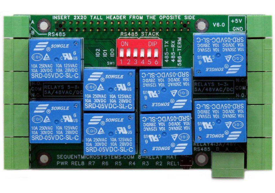
Eight Relays 4A/120V 8-Layer Stackable HAT for Raspberry Pi
Eight Relays 4A/120VAC, 24VDC N.O./N.C. contacts and LED indicators; RS485 Port. -
 In stock
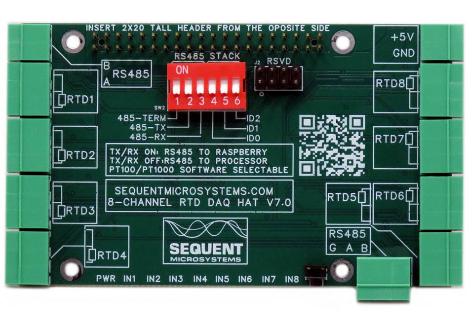
RTD Data Acquisition 8-Layer Stackable HAT for Raspberry Pi
Eight Channel RTD Data Aquisition HAT; 0.01% accuracy through calibration; PT100/1000 Sensors; RS485/MODBUS, Watchdog. -
 In stock
Sixteen LV Digital Inputs 8-Layer Stackable HAT for Raspberry Pi
Sixteen 3V-24V Opto-isolated Inputs with LED indicators; RS485/MODBUS, Hardware Watchdog. -
 In stock
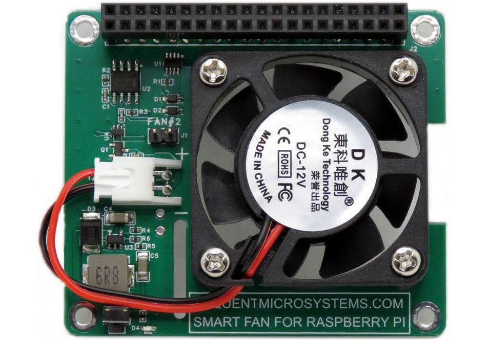
Smart Fan HAT the Best Cooling Solution for Raspberry Pi
PWM controlled 40x40x10mm Fan keeps Raspberry Pi temperature constant; Stackable with any other HAT.
