


RTD Data Acquisition 8-Layer Stackable HAT for Raspberry Pi
Eight Channel RTD Data Aquisition HAT; 0.01% accuracy through calibration; PT100/1000 Sensors; RS485/MODBUS, Watchdog.
Overview
Eight-channel RTD data acquisition HAT for Raspberry Pi supporting both PT100 and PT1000 sensors, selected in software — no jumpers required. Uses 24-bit delta-sigma ADCs for factory accuracy of 0.1%, calibratable to 0.01% in the field. Eight-layer stackable for up to 64 RTD channels per Raspberry Pi. Includes RS485/MODBUS, hardware watchdog, and programmable status LEDs. Compatible with all Raspberry Pi from Zero to 5.
- PT100 sensors: −200°C to 765°C range · PT1000 sensors: −50°C to 500°C range
- Software-selectable sensor type — no jumpers or hardware changes required (V7+)
- 24-bit delta-sigma ADCs · Factory accuracy 0.1% · Field calibration to 0.01%
- Maximum acquisition speed: 40 cps · 3-wire circuit design compensates for lead resistance
- RS485/MODBUS port · Hardware watchdog · Eight programmable threshold LEDs
- Eight-layer stackable — up to 64 RTD channels · Uses only I2C — 24 GPIO pins remain free
- 5V powered from Raspberry Pi or own connector · Resettable fuse · Compatible with all Raspberry Pi Zero through 5
Works with Open Automation Software
Compatible with widely used tools for control, monitoring, and system integration.
 |
 |
 |
 |
 |
 |
 |
INTERFACES AND I/O
| I/O's | Communication | Software Integration |
|---|---|---|
| • Eight RTD Inputs — PT100 or PT1000 (software selectable) | • I2C Port to Raspberry Pi | • Command Line |
| • — PT100: −200°C to 765°C | • RS485/MODBUS Port | • Python Library |
| • — PT1000: −50°C to 500°C | • Node-RED Nodes | |
| • 24-bit Delta-Sigma ADC · 40 cps max · 3-wire input | • CODESYS Driver | |
| • Eight Programmable Threshold Status LEDs | • OpenPLC Module | |
| • Push Button for Safe Shutdown (GPIO 26) | • Home Assistant | |
| • Arduino Library | ||
| Other Features | ||
| • Factory accuracy 0.1% · Field calibration to 0.01% · On-board hardware watchdog and resettable fuse | ||
| • Eight-layer stackable — up to 64 RTD channels · Uses only I2C — 24 GPIO pins remain free | ||
| • 5V powered from Raspberry Pi or own connector · 50mA consumption · Compatible with all Raspberry Pi Zero through 5 | ||
| • CE Certified for EU applications | • Pluggable Connectors 26–16 AWG wires | |
DESCRIPTION
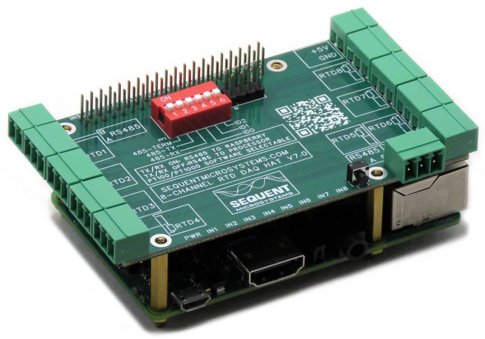
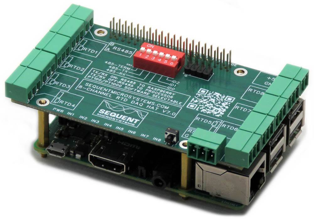
The RTD Data Acquisition HAT turns Raspberry Pi into a compact and accurate temperature acquisition system. It supports up to eight PT100 or PT1000 sensors — sensor type is selected in software with no jumpers or hardware changes required (V7+). Using 24-bit delta-sigma ADCs, the card achieves better than 0.1% factory accuracy, calibratable to 0.01% in the field using a precision 100Ω resistor. Up to eight cards stack on one Raspberry Pi for 64 RTD channels.
V7 supports both PT100 (−200°C to 765°C) and PT1000 (−50°C to 500°C) sensors, selected in software. 3-wire input configuration factors out lead wire resistance for accurate measurements. Maximum acquisition speed: 40 conversions per second.
Factory accuracy: 0.1%. Field calibration using a high-precision 100Ω resistor achieves 0.01% precision. Two-point calibration stores correction coefficients in flash; results are reflected in all subsequent resistance and temperature readings.
Eight LEDs with software-configurable thresholds can activate when an input exceeds a preset temperature or resistance value. Useful for visual alarming in industrial monitoring applications.
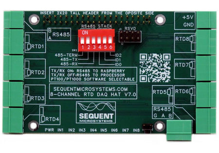
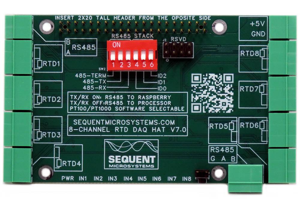
RS485 port configured via the onboard DIP switch (TX and RX positions). TX+RX ON: Raspberry Pi drives the RS485 bus directly as a passive bridge. TX+RX OFF: local processor operates as MODBUS RTU slave. Full register map available on GitHub.
Hardware watchdog automatically power-cycles the Raspberry Pi if the software becomes unresponsive, ensuring continuous operation in unattended deployments. A push button at the card edge (GPIO 26, pin 37) enables safe shutdown without keyboard or monitor.
Up to eight cards stack on one Raspberry Pi for 64 RTD channels. Three DIP switch positions (ID0, ID1, ID2) select the stack level. Cards can be stacked in any order and mixed freely with other Sequent HAT types.
TECHNICAL DETAILS
CARD LAYOUT

MECHANICAL SPECIFICATIONS
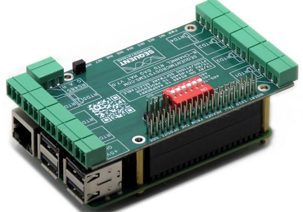
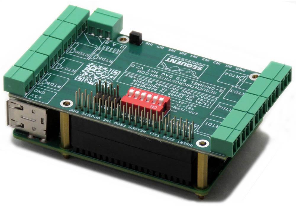
The Eight RTD DAQ Card conforms to the Sequent Microsystems Industrial HAT format for Raspberry Pi. All cards in this family share the same mechanical dimensions and connector layout, and feature nine LEDs and a pushbutton located in identical positions. This standardized design simplifies system integration and allows multiple cards to be used within a common enclosure.

DIP SWITCH AND STACKING
The onboard six-position DIP switch configures both the stack address and the RS485 port behavior. Cards of different Sequent HAT types can be freely mixed in the same stack.
| Switch | Name | Function |
|---|---|---|
| TERM | RS485 termination | Enable on the last card in an RS485 chain to prevent signal reflections |
| TX | RS485 TX select | ON: Raspberry Pi drives RS485 directly |
| RX | RS485 RX select | ON: Raspberry Pi receives RS485 directly |
| ID2 | Stack ID bit 2 | Binary stack address bit 2 (MSB) |
| ID1 | Stack ID bit 1 | Binary stack address bit 1 |
| ID0 | Stack ID bit 0 | Binary stack address bit 0 (LSB) — sets card level 0–7 |
ELECTRICAL SPECIFICATIONS
Power supply: The card requires 5V to operate. It can be powered from the Raspberry Pi GPIO bus or from its own pluggable power connector. Operating current is 50mA.
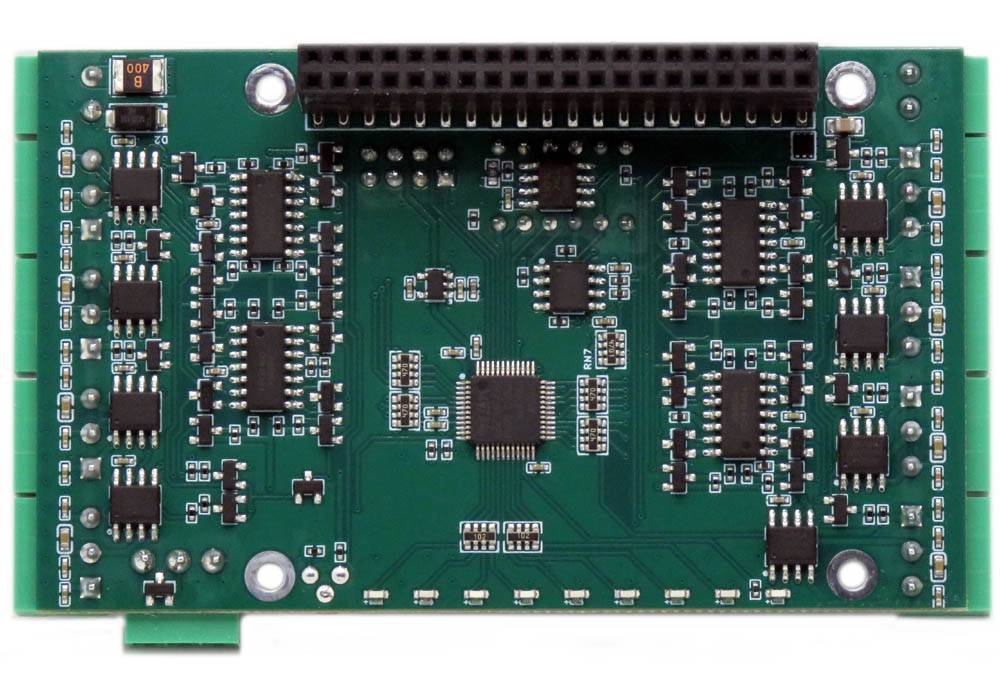
RTD inputs: Eight channels using 24-bit delta-sigma ADCs. Factory accuracy: 0.1%. Maximum acquisition speed: 40 conversions per second. 3-wire input circuit design compensates for lead wire resistance. Field calibration with a precision 100Ω resistor achieves 0.01% accuracy.
POWER REQUIREMENTS
Power supply: The card requires 5V to operate and can be powered from the Raspberry Pi GPIO bus or from its own pluggable power connector. Operating current is 50mA. An onboard resettable fuse protects against accidental shorts.
PLUGGABLE CONNECTORS
All RTD inputs connect to 3.5mm pitch pluggable screw terminal connectors, accepting wire gauges from 26 to 16 AWG. Connectors can be unplugged from the board for convenient field wiring and debugging without disturbing the rest of the installation.
FIELD CALIBRATION
The A/D converter measures temperature by sourcing a precise 1 mA excitation current through the RTD sensor and measuring the resulting voltage. The current source is referenced to an 820 Ω, 0.1% precision resistor, which limits the accuracy of an uncalibrated board to approximately 0.1%.
For applications requiring higher accuracy, each input channel supports two-point calibration. Using a precision 100 Ω reference resistor, calibration accuracy better than 0.01% can be achieved. For best results, select two calibration points that are as far apart as possible within the measurement range.
Calibration coefficients are stored in non-volatile flash memory and are automatically applied to all subsequent resistance and temperature measurements.
First, short the RTD input to be calibrated and issue the following command:
megartd <id> c[alibrate] <channel> 0
Next, connect a precision 100 Ω resistor (0.01% tolerance recommended) to the same input and issue:
megartd <id> c[alibrate] <channel> 100
While any precision resistor between 0 Ω and 100 Ω may be used for calibration, the best results are obtained with a resistor value as close as possible to 100 Ω, which corresponds to the upper calibration point.
The resistance-to-temperature conversion is performed using the equation:
T = (R − R₀) / (R₀ × k)
where:
T = temperature in °C
R = measured sensor resistance
R₀ = resistance at 0°C (100 Ω for PT100, 1000 Ω for PT1000)
k = 0.00385
If higher conversion accuracy is required, the software can also return the raw resistance values, allowing users to implement custom polynomial conversion algorithms.
To restore the factory calibration values for all channels, issue the command:
megartd <id> rc[alibrate]
The RESET command restores all calibration coefficients to their factory values. After a reset, the calibration procedure can be repeated at any time.
COMMUNICATION INTERFACES
HARDWARE WATCHDOG
The RTD Data Acquisition HAT includes a hardware watchdog that ensures your system automatically recovers if the Raspberry Pi software becomes unresponsive. The watchdog is disabled at power-up and activates after it receives the first reset command from the Raspberry Pi.
| Watchdog Parameters | |
|---|---|
| Initial timeout period | Configurable — allows time for Raspberry Pi to boot and start the application |
| Running timeout period | Configurable — normal operating timeout |
| Off period | Configurable — duration the Raspberry Pi power is cut when timeout triggers |
| Reset counter | Stored in non-volatile flash; can be read or cleared at any time |
For a full list of watchdog commands, run: rtd -h
COMPATIBILITY
| Interface | I2C |
| GPIO used | GPIO2 (SDA), GPIO3 (SCL) — 2 pins only; remaining 24 GPIO pins stay free |
| Max stack | 8 cards of each type; different Sequent HATs can be freely mixed with virtually no upper limit on total I/O |
| Compatible with | All Raspberry Pi versions from Zero to 5 (40-pin GPIO header) |
FIRMWARE UPDATE
The onboard microcontroller firmware can be updated in the field. The update tool downloads the latest firmware from Sequent Microsystems' servers and flashes it to the board over I2C.
Running the Update
~$ cd ~/rtd-rpi/update/
~/rtd-rpi/update$ ./update <id>
Replace <id> with the board stack address (0-7). Full instructions including recovery procedures are available at:
https://github.com/SequentMicrosystems/rtd-rpi/tree/master/update
DOWNLOADS
| User's Guide (PDF) | Schematics (PDF) | CAD | Software & Integrations |
|---|---|---|---|
| User's Guide V6.0 | Schematic V6.0 | 2D CAD Drawing | Command Line |
| User's Guide V6.2 | Schematic V6.2 | 3D STEP Model V6.2 | Python Library |
| User's Guide V6.3 | Schematic V7.0 | 3D STEP Model V6.3 | Node-RED Nodes |
| User's Guide V8 | Schematic V8.0 | 3D Printing Enclosure | MODBUS Interface |
| CODESYS Library | |||
| Arduino Library | |||
| Home Assistant Integration |
COMPLIANCE
RoHS and REACH Compliance Declaration
WHAT'S INCLUDED
When you purchase the RTD Data Acquisition HAT you will receive the following items:
| 1. RTD Data Acquisition HAT for Raspberry Pi |
|---|
 |
| 2. Mounting Hardware | |
|---|---|
 |
|
| 3. Connector Plugs for all Inputs | |
|---|---|
 |
|
QUICK START
- Plug your card on top of your Raspberry Pi and power up the system.
- Enable I2C communication on Raspberry Pi using
raspi-config. - Install the software from GitHub:
~$ git clone https://github.com/SequentMicrosystems/rtd-rpi.git~$ cd /home/pi/rtd-rpi~/rtd-rpi$ sudo make install~/rtd-rpi$ rtd
The program will respond with a list of available commands. To read more about the CLI, please refer to the README file. If you would rather use a different platform, you can access the same functionality through dedicated, ready-to-use integrations in the Downloads tab above.
Expand Your System
-
 In stock
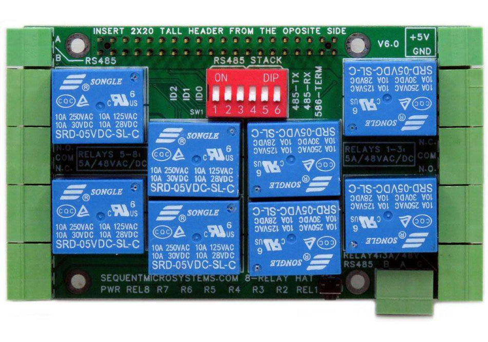
Eight Relays 4A/120V 8-Layer Stackable HAT for Raspberry Pi
Eight Relays 4A/120VAC, 24VDC N.O./N.C. contacts and LED indicators; RS485 Port. -
 In stock
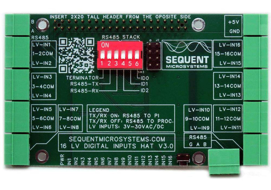
Sixteen LV Digital Inputs 8-Layer Stackable HAT for Raspberry Pi
Sixteen 3V-24V Opto-isolated Inputs with LED indicators; RS485/MODBUS, Hardware Watchdog. -
 In stock
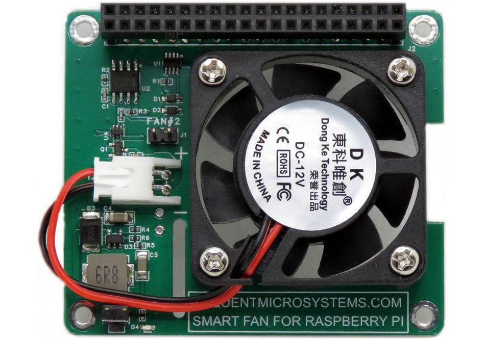
Smart Fan HAT the Best Cooling Solution for Raspberry Pi
PWM controlled 40x40x10mm Fan keeps Raspberry Pi temperature constant; Stackable with any other HAT. -
 In stock
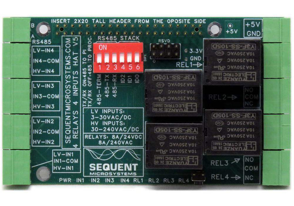
Four Relays four HV Inputs 8-Layer Stackable HAT for Raspberry Pi
Four Relays 8A/240VAC; Four opto-isolated Inputs 3V-240V; RS485/MODBUS; Quadrature encoder, PPS counters, PWM inputs;


