Good evening,
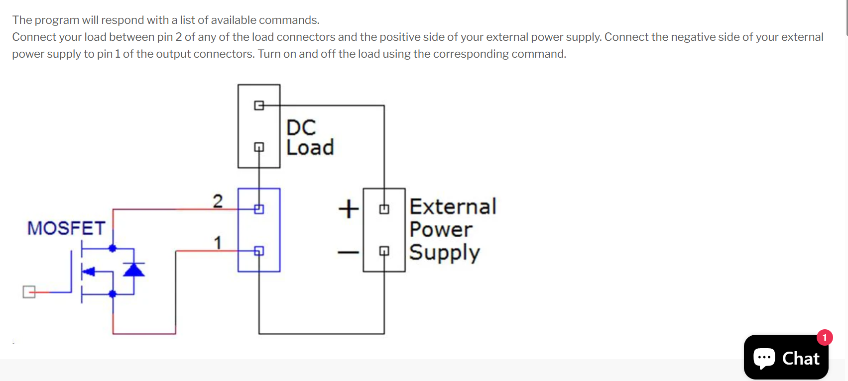
I am a little unclear about the wiring on the above card. The "Quick Start" tab on the product page has the above diagram, but its not exactly clear which is pin one and pin 2. The board is labelled "OUT" and IGND.
Does the relay need to be after the DC Load as shown?
And which of OUT or IGND is connected to the battery positive?
Appreciate any clarification
James
Hi,
IGND is pin 1, and OUT is pin 2.
You can vary the schematics as long as current flows from OUT (pin2) to IGND(pin 1).
Thanks for your time
James
I bought the
Eight RELAYS 8-Layer Stackable HAT for Raspberry Pi. Today ... it started active strange.
Using the python,
>>> import lib8relind
>>> lib8relind.get_all(0)
0
>>>
>>> lib8relind.set_all(0,255)
>>> lib8relind.set(0,1,1). ib8relind.set(0,2,1) ...
...
as I change the pin number, the leds light in a strange pattern. (looking at the board upside down)
1-3-7-5-6-8-4-2 ... power light
should be. 1-2-3-4-5-6-7-9
Hi Thomas,
Please tell me the card version you are using.
I just tested with the latest version (6.2), and all the commands are correct.
Good evening,
I have just gotten around to properly testing this board and it is not behaving how I would expect.
I was under the impression I could control 4 separate DC circuits up to 12 amps each (at 12V)
However, the IGDN pins are all connected so if one relay fires all the outputs are energised and loads activated off the one relay.
I know I must have missed something, but I cant for the life of me figure out what
Any help would be appreciated
James
Hi,
If you can share the connection diagram, I might point you in the right direction.
Alex.
Hi Alex, Please find attached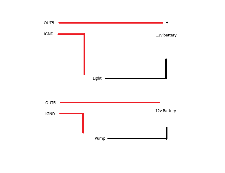 .
.
If i turn on the light, both the light and pump comes on, and vise versa. Id like to control them individually
In the first message of this topic, you posted a schematic that is the correct way to connect the load.
The one you just sent will not work.
In your case
- first load: +12V -> ligt (one terminal); light (second terminal) -> OUT5; -12V -> IGND
- second load +12V -> pump(+ terminal); pump(- terminal) -> OUT6; -12V -> IGND
Try this and let me know how is working
Alex
Ah I see
I took "You can vary the schematics as long as current flows from OUT (pin2) to IGND(pin 1)" to mean that I could move the load in regard to "Does the relay need to be after the DC Load as shown?"
Thanks
James
Because the IGND pin is connected between every 4 channels, you cannot do that.
Because all 4 high-current channels have the same GND1 and all 4 high-voltage channels have the same GND2 (GND1 is galvanically isolated from GND2, and both are isolated from the Raspberry GND), if you use one high-voltageand one high-current channel, you can do your connection (no other channel can be used in that scenario).
We could isolate each channel, but that would increase the size and cost of the card significantly.
Bottom line: connect your load between +12V and OUTx, and it will work as expected.
Alex.