


Arduino Uno, Nano, Teensy, Feather or ESP32 Raspberry Pi Replacement Kit
Replace Raspberry Pi with Arduino UNO or NANO, TEENSY, FEATHER or ESP32. Identical size with Pi HATs; Soldering required.
Overview
The Arduino Uno/Nano/Teensy/Feather/ESP32 Raspberry Pi Replacement card lets you use any Raspberry Pi HAT or add-on card with a low-cost Arduino UNO, NANO, TEENSY, FEATHER, or ESP32 processor instead of a Raspberry Pi. It has the same mechanical form factor and 2x20 pin connector as a Raspberry Pi HAT, so any I2C-based Sequent Microsystems card plugs straight on top.
- Mechanical dimensions identical with Raspberry Pi HAT
- Replace Raspberry Pi with Arduino UNO or NANO, TEENSY, FEATHER or ESP32
- All required hardware included for any one of the five families
- Connector soldering required
- Arduino Uno, Nano, Teensy, Feather or ESP32 Raspberry Pi Replacement
Works with Arduino Libraries
Compatible with growing set of Arduino libraries for controlling Sequent Microsystems HATs.
 |
INTERFACES AND I/O
| Processor Sockets | Communication | Software Integration |
|---|---|---|
| • Arduino UNO socket (J4) | • I2C pass-through to plugged-in HAT | • 8-Relays Arduino Library |
| • Arduino NANO socket (J5) | • 2x20 pin Raspberry Pi HAT GPIO passthrough | • 8-Mosfets Arduino Library |
| • TEENSY socket (J2) | ||
| • FEATHER socket (J3) | ||
| • ESP32 socket (J6) | ||
| Other Features | ||
| • Mechanical dimensions identical with Raspberry Pi HAT | ||
| • All required hardware included for any one of the five processor families | ||
| • Ships unassembled — connector soldering required to match your target processor | ||
DESCRIPTION
The Arduino Uno Raspberry Pi Replacement card let's you use any HAT or add-on card with any of the following low cost processors: Arduino UNO or NANO, TEENSY, FEATHER or ESP32.
The card has the same form factor as a Raspberry Pi and an identical 2x20 pin connector where you can plug any Raspberry Pi IO card which uses the I2C port for communication. On the opposite side, the card has male or female socket adapters where you can plug the replacement processor.
Since the card can accommodate five different families of processors, it comes unassembled. You will need to solder the 2x20 pin connector for any Raspberry Pi add-on card, two pull-up resistors on the I2C lines, and the connectors that fit your target processor.
Solder the R1 and R2 resistors, the 2x20 pin connector, and the breakout pins for connector J4. Plug the UNO into the J4 connectors and secure with standoffs if necessary.
Solder the R1 and R2 resistors, the 2x20 pin connector, and the female headers for connector J5. Plug the NANO into the J5 connectors.
Solder the R1 and R2 resistors and the 2x20 pin connector. Solder the TEENSY directly on the J2 connector, or use female headers if the TEENSY pins are already soldered.
Solder the R1 and R2 resistors and the 2x20 pin connector. Solder the FEATHER directly on the J3 connector, or use female headers if the FEATHER pins are already soldered.
Solder the R1 and R2 resistors and the 2x20 pin connector. Solder the ESP32 directly on the J3 connector, or use female headers if the ESP32 pins are already soldered.
TECHNICAL DETAILS
ASSEMBLY
In all configurations, the 2x20 pin connector is installed on top, and the processor adaptor connectors on bottom. The 2 pull-up resistors can be installed on either side. Shown here is the bottom view of an assembly of the Raspberry Pi Replacement with ARDUINO-UNO.

REPLACING RASPBERRY PI WITH TEENSY
Solder the R1 and R2 resistors and the 2x20 pin connector. If your TEENSY does not have the pins soldered, you can break two 14 pin sections from the 40 pin male header provided and solder the TEENSY directly on the J2 connector.
If the TEENSY has the pins soldered, break 2 pins from each of the 16 pin female headers provided, and solder the female headers into the J2 connector as shown. Plug the TEENSY into J2 connector.

REPLACING RASPBERRY PI WITH UNO
Solder the R1 and R2 resistors and the 2x20 pin connector. Break the 40 pin male header provided into 6, 2 x 8, and 10 pins. Solder the breakout pins on the footprint of connector J4 as shown. Plug the UNO into the J4 connectors and secure with standoffs (not provided), if necessary.

REPLACING RASPBERRY PI WITH ESP32
Solder the R1 and R2 resistors and the 2x20 pin connector. If your ESP32 does not have the pins soldered, you can break two 15 pin sections from the 40 pin male header provided and solder the FEATHER directly on the J3 connector.
If the FEATHER has the pins soldered, break 1 pin from each of the 16 pin female headers provided, and solder the female headers into the J6 connector as shown. Secure the ESP32 processor with stand-offs (not provided) if necessary.

REPLACING RASPBERRY PI WITH FEATHER
Solder the R1 and R2 resistors and the 2x20 pin connector. If your FEATHER does not have the pins soldered, you can break a 12 pin and a 16 pin sections from the 40 pin male header provided and solder the FEATHER directly on the J3 connector.
If the FEATHER has the pins soldered, break 4 pins from one of the 16 pin female headers provided, and solder the female headers into the J3 connector as shown. Plug the FEATHER into the J3 connector and secure with extra stand-offs (not provided) if necessary.

REPLACING RASPBERRY PI WITH NANO
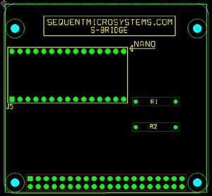
Solder the R1 and R2 resistors and the 2x20 pin connector. Cut or pull one end pin of the two 16 pin female headers provided. Solder the female headers on the footprint of connector J5 as shown bellow. Plug the NANO into the J5 connectors.
COMPATIBILITY
| Interface | I2C |
| Supported processors | TEENSY 3.2/3.5/3.6/4.0/4.1, Arduino UNO, Arduino NANO, Adafruit FEATHER, ESP32 DEVKIT V1 |
| Other processors | Any processor with an I2C port can be used if connected directly to the card's I2C port; the electrical and mechanical constraints of the card are what limit the officially supported list above |
| Compatible with | Any Raspberry Pi HAT or add-on card that communicates over the I2C port |
APPLICATION EXAMPLE
The following shows one of the easiest and cheapest ways to control AC or DC loads from the Internet. Using the Raspberry Pi replacement card, the ESP32 processor and the 8-RELAY Card, this setup lets you control up to 8 loads of 120V and 8A each from your browser.

DOWNLOADS
| User's Guide (PDF) | Schematics (PDF) | CAD | Software & Integrations |
|---|---|---|---|
| User's Guide | Schematic V1.0 | 8-Relays Arduino Library | |
| 8-Mosfets Arduino Library |
WHAT'S INCLUDED
When you purchase the Raspberry Pi Replacement Kit you will receive the following items:
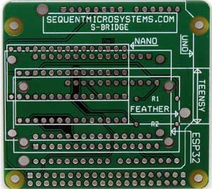
| 1. Bare PCB Adapter Board |
|---|
 |
| 2. 2x20 Male Pin Header |
|---|
 |
| 3. Two 2x16 Female Headers |
|---|
 |
| 4. One 1x40 Breakable Male Pin Header |
|---|
 |
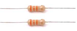
| 5. Two 2.2K I2C Pull-Up Resistors |
|---|
 |
QUICK START
- Solder the 2x20 pin connector and the two 2.2K I2C pull-up resistors onto the board.
- Solder the connector set matching your target processor (see Technical Details above for Uno, Nano, Teensy, Feather, or ESP32).
- Plug your Raspberry Pi HAT or add-on card into the 2x20 connector on top, and plug your processor into its socket on the bottom.
- Install the matching Arduino library for your HAT (e.g. 8-Relay or 8-Mosfet) from GitHub and refer to its README for usage.
To read more about the available libraries, please refer to the 8-Relays and 8-Mosfets README files. More libraries will be available soon.
Expand Your System
-
 In stock
DIN-RAIL Kit Type2 Perpendicular Mount for Raspberry Pi
Install Raspberry Pi and any number of HATs perpendicular to the DIN-Rail; One kit for up to 5 HATs. -
 In stock
Smart Fan HAT the Best Cooling Solution for Raspberry Pi
PWM controlled 40x40x10mm Fan keeps Raspberry Pi temperature constant; Stackable with any other HAT. -
 In stock
DIN-RAIL Kit Type1 Parallel Mount for Raspberry Pi
Install Raspberry Pi and multiple HATs parallel on the DIN-Rail; 90% rotation; Raspberry Pi 1 to 5. -
 In stock
Super Watchdog HAT with UPS Battery Backup for Raspberry Pi
Industrial-grade watchdog and UPS backup to keep your Raspberry Pi running safely.


