

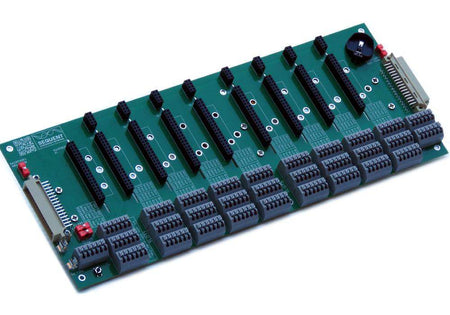


I/O Back Panel for Raspberry Pi Industrial Automation - 8 Slot Version
Dedicated Raspberry Pi/Compute Module Slot plus eight expansion slots; 2xRS485, 2xRS232, CAN, RTC, Watchdog; Expandable to 8 units
BACK PANEL BASED RASPBERRY PI INDUSTRIAL AUTOMATION
Revolutionize Industrial Automation with the Raspberry Pi Back Panel
Powerful. Scalable. Built for Industry.
Unlock the full potential of the Raspberry Pi 5 in your industrial automation projects with Sequent Microsystems' new Back Panel system—a game-changing alternative to traditional HAT-based expansion.
Harness the power of a 2.4GHz quad-core Cortex-A76 processor and up to 16GB of RAM, now supported by a modular, professional-grade platform designed specifically for real-world control systems.
Why Upgrade from HAT to HOP?
The traditional HAT (Hardware Attached on Top) format was never built for the demands of industrial environments—limited expansion, messy wiring, no mounting standard, and a weak 5V power system.
Sequent's HOP (Hardware On Panel) architecture changes everything:
-
✅ Unlimited horizontal I/O expansion
-
✅ Twice the board area for richer functionality (84×90mm)
-
✅ Clean, organized wiring with predefined connection plans
-
✅ 2×RS485, 2×RS232, and 2×CAN ports for industrial protocols
-
✅ Built-in hardware watchdog and real-time clock
-
✅ 24V industrial power input
-
✅ DIN-rail mountable for easy installation
- Ambient operating temperature: -40°C to 85°C
Built for Engineers, Ready for Deployment
The Back Panel for Raspberry Pi supports legacy HATs via an adapter and introduces a new open-source card standard, making it easy to prototype, test, and deploy scalable control systems—all on the Raspberry Pi platform you know and trust.
OVERVIEW
Back Panel for Raspberry Pi Overview
The Sequent Microsystems Back Panel for Raspberry Pi is engineered to meet the rigorous demands of industrial automation, offering a scalable and modular platform that overcomes the inherent limitations of traditional Raspberry Pi HAT designs.
Key Technical Highlights
-
Processor Compatibility: Designed for Raspberry Pi 3, 4, and 5 models, leveraging the Pi 5’s 2.4GHz quad-core Cortex-A76 CPU and up to 16GB LPDDR4X RAM to support complex control and data processing tasks.
-
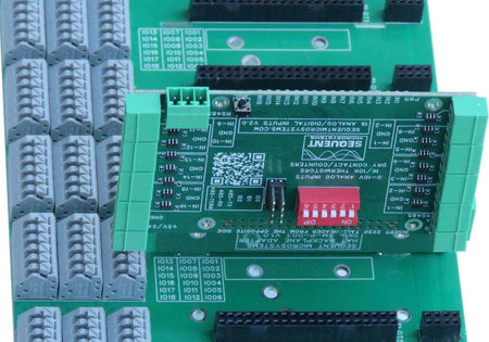
Modular I/O Architecture: Eight identical I/O slots with standardized connectors support up to eight mixed or identical I/O cards, each with dedicated RS485 transceivers, serial interfaces, and isolated signals.
-
Robust Industrial Interfaces: Includes dual RS485 ports (one shared across all I/O cards enabling MODBUS control), dual RS232 ports, CAN bus connectivity via SPI, and hardware watchdog functionality to maintain system integrity.
-
Reliable Timekeeping: Integrated Maxim DS1307 Real Time Clock with battery backup, accessible via I²C, provides precise time and date functions critical for industrial logging and scheduling.
-
Power and Connectivity: Powered by an external 24V supply stepped down onboard to 5V/5A; spring-loaded terminal blocks ensure secure field wiring and industrial-grade reliability.
-
Expandability and Compatibility: Supports existing HATs through custom adapters and introduces a new open-source standard for I/O cards, facilitating flexible system design and future-proofing.
-
Software Integration: Fully compatible with industrial software stacks such as CODESYS and OpenPLC, enabling rapid deployment of control algorithms and automation logic.
Designed for Industrial Control and Automation
This platform is ideal for engineers and integrators requiring a scalable, reliable, and maintainable industrial I/O solution built around the versatile Raspberry Pi ecosystem.
FEATURES
Key Features
-
Unlimited horizontal I/O expansion – Scales with your project needs
-
Large board footprint (84×90mm) – More space for industrial-grade components
-
Clean wiring layout – Predefined wiring plan simplifies installation
-
Multiple industrial interfaces – 2×RS485, 2×RS232, CAN
-
Built-in hardware watchdog – Ensures system reliability
-
Real-time clock (RTC) – Accurate timekeeping for automation tasks
-
24V industrial power input – Compatible with standard control cabinets
-
DIN-rail mountable – Easy integration into industrial enclosures
-
Supports legacy HATs – Backward compatibility via adapter
-
Open-source I/O card standard – Encourages custom and community expansion
TECHNICAL SPECS
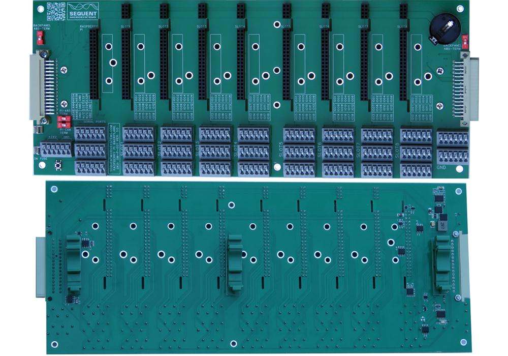
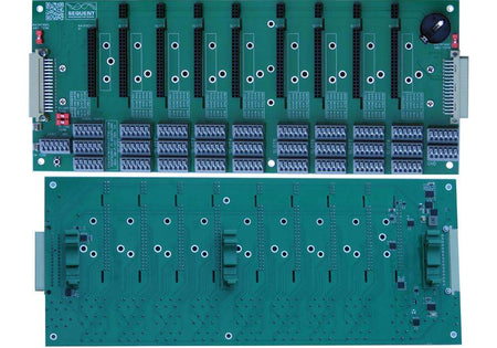
The Back Panel for Raspberry Pi measures 317mm x 127mm. It can be installed directly on a DIN-Rail using three plastic brackets provided.
POWER REQUIREMENTS
The Back Panel is powered by an external 24V DC power supply. An onboard step-down converter regulates this input to provide a stable 5V output with up to 5A current, powering the Raspberry Pi and all connected I/O cards.
The 24V input is connected via a spring-loaded terminal block located at the lower-left corner of the panel, ensuring secure and reliable wiring for industrial environments.
TERMINAL BLOCKS

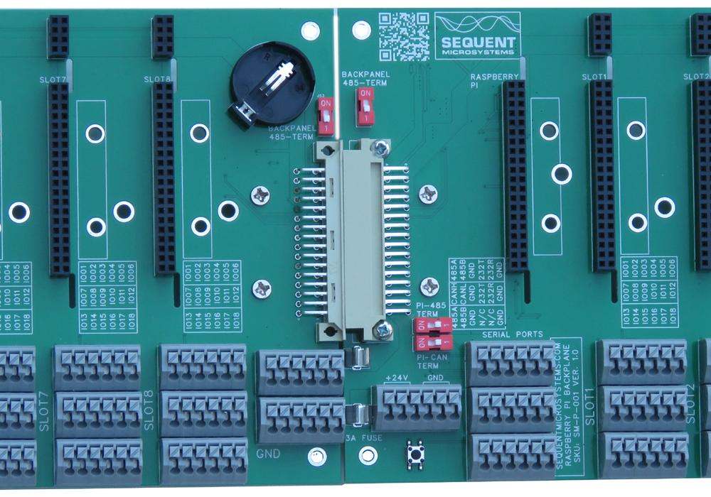
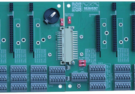
The power connector, located at the upper-left corner of the Back Panel, is used to supply 24V DC power to the system. It features a 6-pin terminal block, with the left three pins designated for +24V and the right three for GND, ensuring a reliable and redundant power connection.
When using multiple Back Panels in a system, it is recommended to supply 24V power to each panel individually to ensure consistent voltage levels and prevent power drop across the chain.

-
RS232 Port 1 is connected to GPIO pins 7 (TX) and 9 (RX)
-
RS232 Port 2 is connected to GPIO pins 32 (TX) and 34 (RX)
-
RS485 Port 1 is connected to GPIO pins 8 (TX) and 10 (RX)
-
RS485 Port 2 is shared across all I/O cards on the Back Panel and enables MODBUS communication from an external PLC
To ensure proper signal integrity on differential buses, terminator switches are provided for both RS485 ports and the CAN port.
RS485/MODBUS Communication
The second RS485 port is shared across all I/O cards installed on the Back Panel. Each card features its own RS485 transceiver connected to its local processor, allowing individual control via the MODBUS protocol from an external PLC or master device.

CONNECTIVITY
GPIO Pinout Overview

-
Three serial ports on the Raspberry Pi are utilized to implement one isolated RS485 port and two RS232 ports.
-
The SPI port drives a CAN transceiver for CAN bus communication.
-
A push button on the Back Panel is connected to GPIO17, which can be configured to trigger an interrupt on the Raspberry Pi.
-
GPIO26 serves as an interrupt (INT) line routed to all I/O cards and can signal when an input value is out of range or requires attention.
-
GPIO pins 20 and 21 are connected to open-drain MOSFETs, enabling them to control external 24V relays safely.
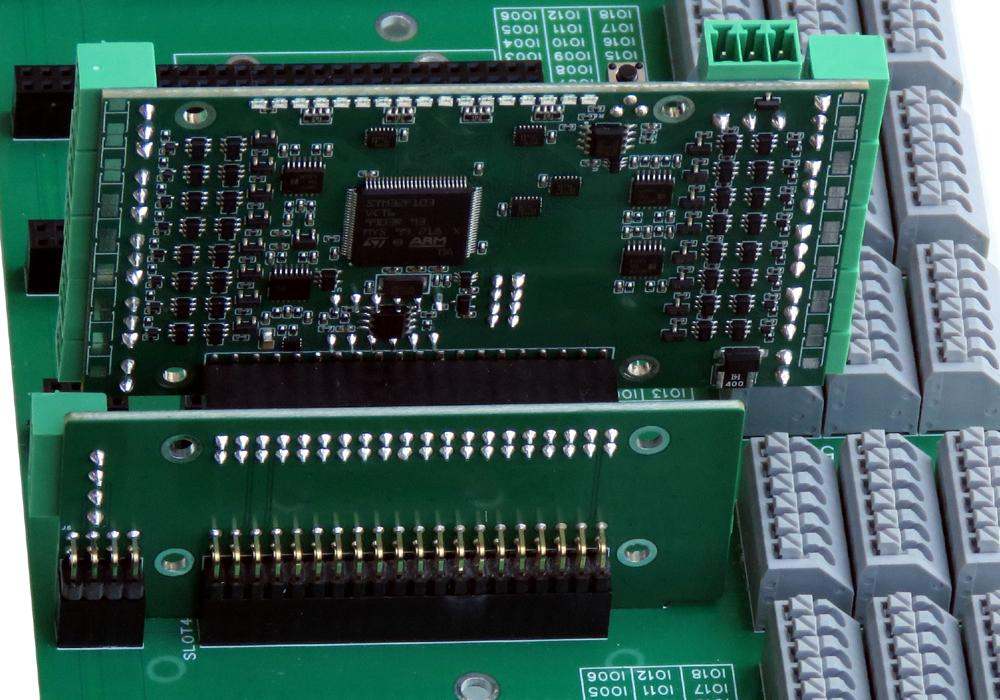
I/O Slots Pinout

The Back Panel features eight identical slots for I/O cards, each spaced at a 1100 mil (1.1 inch) pitch.
-
Each slot includes a 2×20-pin connector routing eighteen signals across three 6-pin spring-loaded connectors.
-
Additionally, each slot has a 2×8-pin connector that distributes 24V, 5V, GND, and a second RS485 port shared among all I/O cards.
-
The I²C signals (SDA on pin 3 and SCL on pin 5) are bussed to all slots for seamless communication.
-
Pin 40 is reserved for the INTERRUPT signal, enabling cards to notify the Raspberry Pi of events.
-
Pin 1 is dedicated to the WATCHDOG trigger, allowing cards to reset the hardware watchdog.
-
Three pins are pre-wired to indicate the stack level—with the leftmost slot as Stack #1 and the rightmost as Stack #8.
-
Up to eight identical or different I/O cards can be installed per Back Panel, enabling flexible and scalable system expansion.
WATCHDOG
The Back Panel features a hardware watchdog designed to cut power to the Raspberry Pi in the event of a system lockup. It monitors I²C activity and ensures the system is responsive.
-
The watchdog can be triggered by any I/O card installed in one of the eight Back Panel slots.
-
The trigger line is shared across all eight I/O slots, enabling any compatible card to monitor and reset the watchdog.
-
All Sequent Microsystems Back Panel I/O cards are capable of issuing the watchdog reset signal.
-
Upon power-up, the watchdog is disabled by default and only becomes active after receiving its first reset signal from the Raspberry Pi.
-
The default timeout period is 120 seconds. If no reset is received within this window, the watchdog cuts power to the Raspberry Pi and then restores it after a 10-second delay.
This feature ensures enhanced system reliability in unattended or mission-critical industrial applications.
To prevent an unintentional system shutdown, the Raspberry Pi must issue a reset command over the I²C interface before the watchdog timer expires. This periodic reset ensures that the system is functioning correctly.
-
Both the initial delay after power-up and the active timeout period can be configured from the command line to match application requirements.
-
The number of watchdog-triggered resets is logged in non-volatile flash memory, allowing for diagnostics and monitoring.
-
This reset count can be read or cleared via simple command-line instructions.
-
All watchdog functions, including configuration and status checks, are accessible through a built-in online help utility, ensuring ease of use and integration.
This configurable hardware watchdog adds a critical layer of protection and visibility for robust, unattended industrial automation deployments.
REAL TIME CLOCK (RTC)
The Back Panel for Raspberry Pi includes a Real Time Clock (RTC) implemented using the Maxim DS1307 chip, enabling accurate timekeeping even during power outages.
-
Time and date data—including seconds, minutes, hours, day, date, month, and year—are accessed via the I²C interface.
-
RTC registers are mapped to I²C address locations 00h to 07h, while 56 bytes of user RAM are available at locations 08h to 3Fh.
-
A CR2032 coin-cell battery socket provides backup power to maintain timekeeping when the system is off.
-
The RTC ENB DIP switch, located in the lower right corner of the board, must be turned ON to enable the RTC.
-
When multiple Back Panels are connected, only one RTC should be active to avoid I²C address conflicts.
This built-in RTC provides essential timekeeping functionality for scheduling, logging, and automation tasks in industrial applications.
EXPANSION
Expansion Capability
The Back Panel for Raspberry Pi is designed for seamless horizontal scalability. Each panel includes mating 2×16 male and female connectors at opposite ends, allowing multiple panels to be physically and electrically daisy-chained together without additional cabling.
-
Buffered I²C Signals: Integrated I²C buffers ensure signal integrity across multiple panels, enabling near-unlimited expansion of I/O capacity without degrading communication performance.
-
Power Distribution: While communication lines are shared, 24V power should be supplied to each panel individually to maintain stable voltage across the system.
-
Slot Addressing: Each slot retains its stack level identification, allowing the Raspberry Pi to identify and communicate with all I/O cards across connected panels.
This modular expansion approach enables compact and scalable deployment of complex industrial control systems, all built on the Raspberry Pi platform.

ADAPTERS
Raspberry Pi Back Panel Adapter
The Back Panel supports Raspberry Pi models 3, 4, and 5 via a dedicated slot adapter. This adapter rotates the Raspberry Pi’s GPIO connector by 90° to align with the Back Panel’s interface, ensuring a compact and reliable connection.
The Raspberry Pi is secured to the adapter using standoffs, while the adapter itself is firmly mounted to the Back Panel with a metal bracket for robust mechanical stability.


Note: When multiple Back Panels are connected together, only one Raspberry Pi can be used to control the entire system.
Existing HATs Back Panel Adapters
Legacy HATs from Sequent Microsystems or third-party manufacturers can be easily integrated with the Back Panel using a specially designed custom adapter, ensuring backward compatibility without sacrificing expandability.


INSTALLATION
Wiring Plan
Each I/O slot on the Back Panel provides 18 signal lines, routed to the front of the panel via three 6-pin spring-loaded terminal blocks. This layout supports both analog and digital I/O signals, enabling clean and organized wiring directly from the bottom of the panel.
-
Consistent Layout: Identical connector orientation and spacing across all slots simplify wiring and labeling.
-
Tool-Free Termination: Spring-clamp terminals allow for quick, reliable field wiring without crimping or soldering.
-
Industrial Signal Support: Designed to handle a wide range of I/O types—analog input/output, digital input/output, counters, relays, etc.
This connector arrangement enables fast installation, easy troubleshooting, and high-density signal management in industrial control enclosures.

SOFTWARE
DOWNLOADS
Back Panel Downloads
Back Panel IO Card Layout V1.0
FAQ
Frequently Asked Questions (FAQ)
Q1: Which Raspberry Pi models are supported?
A: The Back Panel supports Raspberry Pi 3, 4, and 5 models using a dedicated GPIO slot adapter.
Q2: Can I use standard HATs with the Back Panel?
A: Yes. Legacy HATs from Sequent Microsystems and other manufacturers can be used with the Back Panel via a custom adapter.
Q3: How many I/O cards can be installed?
A: Each panel supports up to 8 I/O cards, one per slot. Multiple panels can be connected together for further expansion.
Q4: How do I connect power to the Back Panel?
A: Power is supplied via a 24V DC input through a spring-loaded terminal block on the lower-left corner. An onboard converter provides 5V/5A for the Raspberry Pi and I/O cards.
Q5: Can I connect multiple Back Panels together?
A: Yes. Panels connect using 2×16 expansion headers at each end. I²C signals are buffered for reliable multi-panel operation. Power must be supplied to each panel individually.
Q6: What serial interfaces are available?
A: The Back Panel includes:
-
RS232 (x2)
-
RS485 (x2) — one dedicated to MODBUS communication with I/O cards
-
CAN bus via SPI
All ports are mapped to Raspberry Pi GPIO pins.
Q7: Is the hardware watchdog required?
A: It’s optional but recommended. It monitors I²C activity and can cut and restore power to the Raspberry Pi in case of a software lockup. It activates only after the first reset command.
Q8: How is the RTC configured?
A: A Maxim DS1307 Real Time Clock is included. It connects via I²C and is enabled using the RTC ENB DIP switch. Only one RTC should be active across multiple panels.
Q9: Can I control the system using MODBUS?
A: Yes. The second RS485 port is shared across all I/O cards and supports MODBUS RTU, allowing control from an external PLC or master device.
Q10: Is the system DIN-rail mountable?
A: Yes. The Back Panel is designed for DIN-rail mounting, making it easy to integrate into industrial enclosures.
Expand Your System
-
 Coming soon
16 Analog 4–20 mA Outputs for Raspberry Pi I/O Back Panel
16 analog 4–20 mA outputs with load detection for Raspberry Pi I/O Back Panel. Industrial current-loop control with RS485 MODBUS, OpenPLC, and CODESYS support. -
 Coming soon
16 Universal Inputs for Raspberry Pi I/O Back Panel
16 Universal Inputs for Raspberry Pi I/O Back Panel. Each input software configured to read 0-3.3V, 0-10V, 4-20mA, 1K/10K Thermistors, and Digital Signals -
 Coming soon
6 RTD Inputs 3-wire PT100/PT1000 for Raspberry Pi I/O Back Panel
6 RTD Inputs with software selectable PT100/PT1000 for Raspberry Pi I/O Back Panel. Command Line, Python, RS485 MODBUS, OpenPLC, and CODESYS drivers. -
 Coming soon
8 Analog 4-20mA/0-10V Outputs for Raspberry Pi Back I/O Panel
Eight Analog Outputs with software selectable 4-20mA or 0-10V for Raspberry Pi I/O Back Panel. Command Line, Python, RS485 MODBUS, OpenPLC, and CODESYS.


