


Eight MOSFETS with PWM, Current Sense and Digital Inputs for Raspberry Pi Back Panel
Eight MOSFETS with PWM, up to 8A and 240VDC loads, proportional control with current sensing
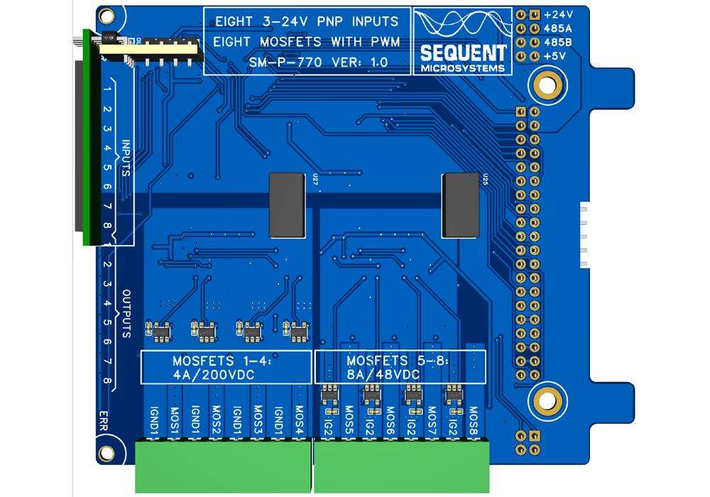
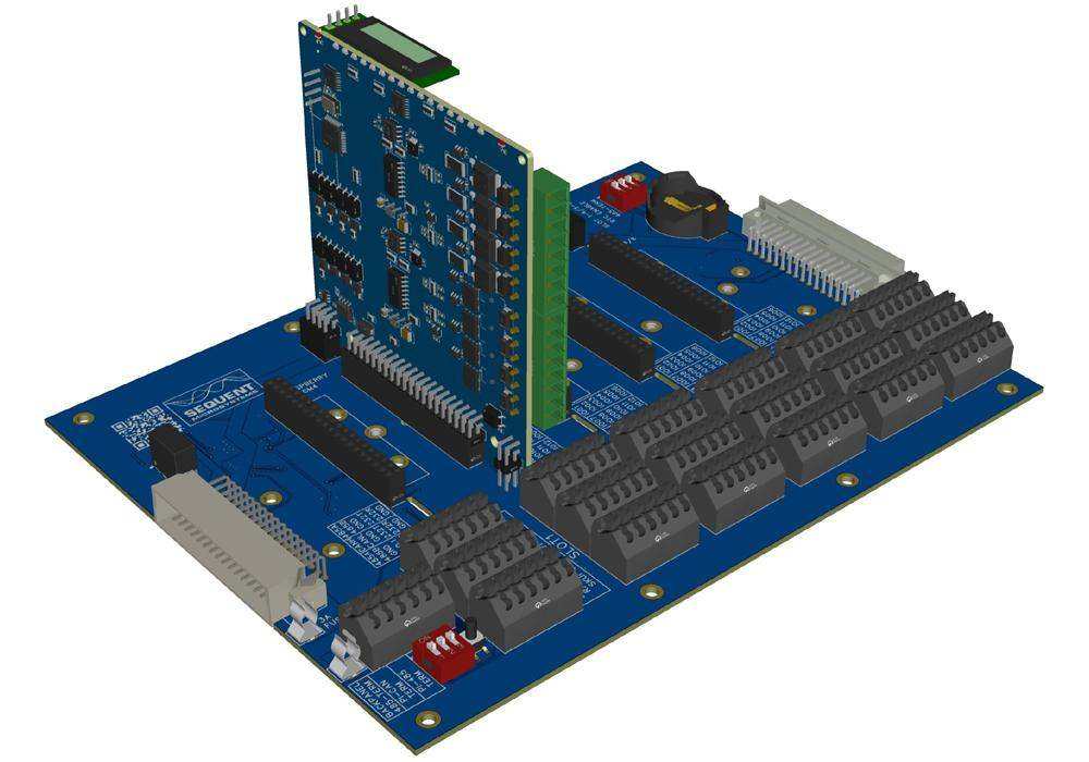
The Eight MOSFETS with PWM card features four high current outputs driving 8A and 48VDC loads and four high voltage outputs driving 4A and 200VDC loads. Each output is PWM controlled and has current measuring and current limiting capability. Each group of four MOSFETS is galvanically isolated. In adition, eight isolated inputs can read active high signals from 3V to 24VAC or DC.
Seamlessly integrated with the Raspberry Pi Back Panel, the card supports Command Line, MODBUS RTU over RS485, OpenPLC, and CODESYS.
FEATURES
Key Features
- Plugs directly into the Raspberry Pi Back Panel - no additional wiring or hardware needed
- Four galvanically isolated 8A/48VDC with 1Khz PWM MOSFET outputs
- Four galvanically isolated 4A/200VDC with 1KHz PWM MOSFET outputs
- Current sensing on all outputs
- Eight optically isolated 3-24VAC/DC, PNP inputs
- LED indicators on all inputs and outputs
- ECCN classification: EAR99
- Open source hardware - schematics available
DESCRIPTION
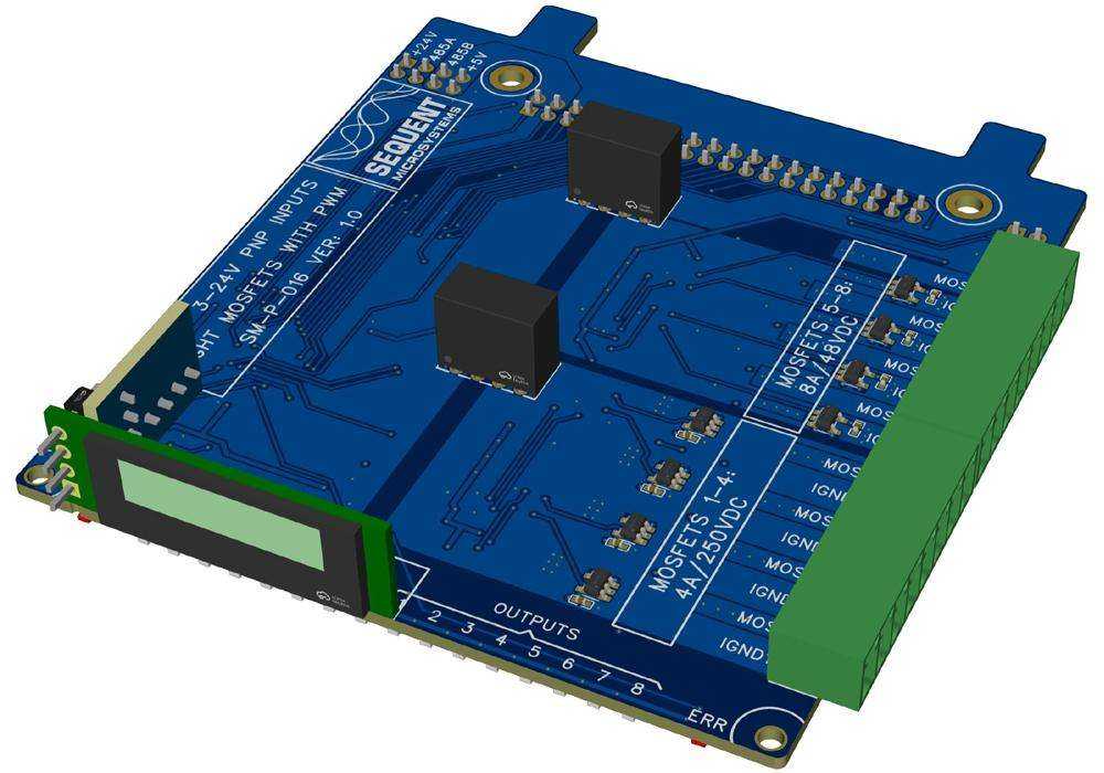
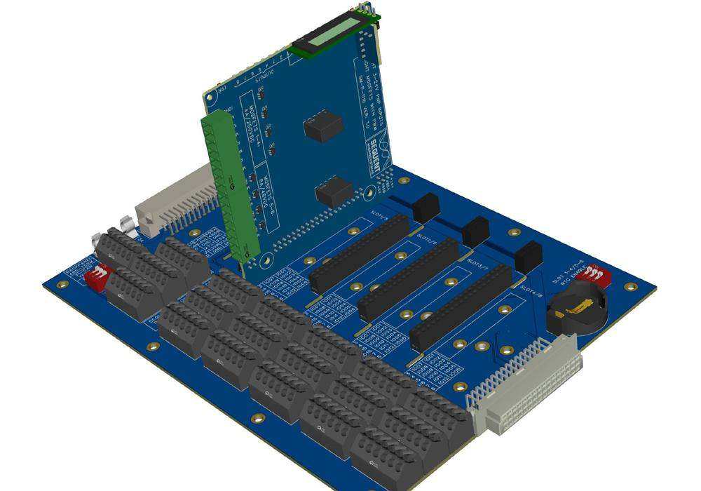
Part of the HOP (Hardware On Panel) family developed by Sequent Microsystems, the Eight MOSFETS with PWM card plugs directly into the Sequent Microsystems Back Panel.
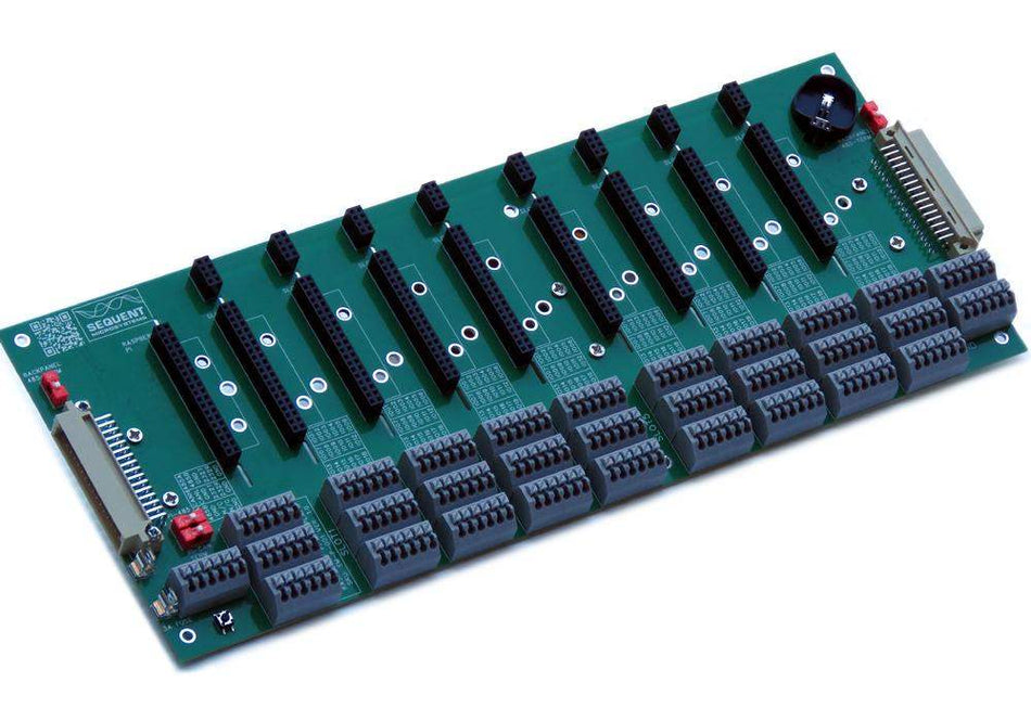
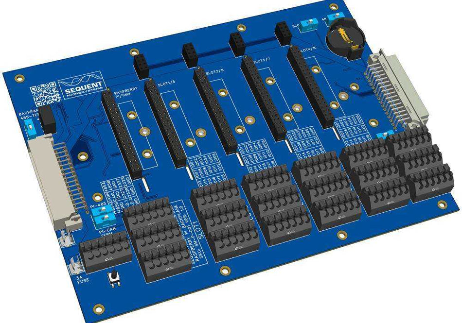
Up to eight HOP cards -of any type- can be installed on a single Back Panel, offering maximum flexibility for industrial automation applications. Multiple Back Panels can be connected horizontally to support larger projects.
Eight PNP inputs are wired to the Back Panel and can be accessed on the spring loaded connectors. Inputs can read active high signals from 3V to 24VAC or DC.
Like all HOP cards, the Eight MOSFETS with PWM card features 18 LED indicators. The power LED blinks when power is applied and the local processor is operational. An error LED illuminates when the dedicated PANIC pin on the Back Panel terminal block is activated. Eight LEDs display the real time status of each input. Eight more LEDs show the status of the outputs.
An RS485 port enables communication with external PLCs or industrial controllers using the industry-standard MODBUS RTU protocol.
Power Requirements
The Eight MOSFETS with PWM card is powered via the Back Panel power connector.
-
MOSFET outputs are open drain and the load has to be powered from an external power supply. Connection to the system ground is optional, depending on your application.
-
The local processor is powered from the 5V rail through a 3.3V LDO regulator and consumes 10 mA.
Error Processing
One pin on the spring-loaded terminal block of the Back Panel is reserved for signaling an error condition. The user can connect this pin to an external contact of their choice. When the error signal is activated, the Eight MOSFETS with PWM card automatically resets all outputs to a predefined default state.
Current Sensing Outputs
Each open-drain output is routed to the output through a Hall Effect-Based Linear Current Sensor IC.. The sensor has a maximum scale of 10A, a bandwidth of 150KHz and 2.6 kVRMS Isolation. This allows the system to calculate the power consumed by each load, limit the current, or disable the output if a predefined current threshold is exceeded.


-
Power Supply: 5V 10mA; 24V 120mA back panel provided.
- Source/Sync outputs: 14bit PWM
- Relays 5-8: N.O. contacts 8A/48VAC/24VDC

DOWNLOADS
3D Printable Enclosure
SOFTWARE
Command Line Drivers
Python Libraries
CODESYS Driver
OpenPLC Module
QUICK START
- Plug the Eight MOSFETS with PWM card on the Back Panel for Raspberry Pi and power up the system.
- Enable I2C communication on Raspberry Pi using raspi-config.
- Install the software from github.com:
- ~$ git clone https://github.com/SequentMicrosystems/8mos-rpi.git
- ~$ cd /home/pi/8mos-rpi
- ~/8relind-rpi$ sudo make install
- ~/8relind-rpi$ 8mos
FAQ
Q: What is the primary function of this card?
A: It provides eight MOSFET output channels (four high-current, four high-voltage) with PWM control and real-time current sensing. It's designed for switching and monitoring DC loads in automation, lighting, and motor control systems using the Sequent Microsystems Back Panel.
Q: What types of loads can I control with this card?
A: The card is designed to drive DC loads only, such as motors, solenoids, LEDs, and heating elements. High-current outputs support up to 8A @ 24 V DC, while high-voltage outputs handle up to 4 A @ 200V DC. It is not suitable for switching AC loads.
Q: How is the stack position determined?
A: Stack position is automatically assigned based on the physical slot the card occupies on the Back Panel. No DIP switches or software configuration are required.
Q: How is the RS485 port configured?
A: The RS485 port is permanently connected to the shared RS485 bus on the Back Panel. It is managed by the onboard processor and supports MODBUS RTU slave communication. The Raspberry Pi does not directly control the RS485 signals on this card.
Q: How is current sensing implemented?
A: Each output is routed through a Fully Integrated, Hall Effect-Based Linear Current Sensor IC with 150kHz Bandwidth and 2.6 kVRMS Isolation with a maximum scale of 10A. The sensor provides a 0-3.3V output proportional with the load current. The output is measured with 12 bit A/D converters. This allows the system to monitor load current, calculate power, and enforce current limits by shutting off outputs when thresholds are exceeded.
Q: Can I use PWM on all outputs?
A: Yes, all eight outputs support software-controlled PWM at 1 kHz, enabling fine-grained control of load power such as motor speed or LED brightness.
Q: Can the card operate without a Raspberry Pi?
A: Yes. When connected via RS485, the onboard processor allows the card to function as a MODBUS RTU slave, making it controllable by any MODBUS-compatible PLC or controller.
Q: Is the card software-compatible with other Sequent MOSFET products?
A: Yes. It uses the same command-line tools and open-source libraries as other Sequent Microsystems cards, including Python and C APIs.
Q: How is the card powered?
A: The card accepts 5 V and 24 V DC through the Back Panel. The 24V supply is used to generate isolated 12V supplies for the MOSFET gate drivers. An onboard regulator generates 3.3V for the local processor.
Q: What happens if a load exceeds the current limit?
A: The card can automatically disable the affected output when current exceeds a user-defined threshold, protecting the load and the system.
Q: Where can I find documentation and examples?
A: Visit Sequent Microsystems’ GitHub repository for open-source code, wiring diagrams, and setup instructions:
👉 https://github.com/SequentMicrosystems
Related products
-
 Coming soon
Back Panel for Raspberry Pi Industrial Automation - Eight Slot Version
Dedicated Raspberry Pi Slot plus eight I/O expansion slots; 2xRS485, 2xRS232, CAN, RTC, Watchdog. Unlimited expandability. -
 Coming soon
Back Panel for Raspberry Pi Industrial Automation - Four Slot Version
Dedicated Raspberry Pi Slot plus four I/O expansion slots; 2xRS485, 2xRS232, CAN, RTC, Watchdog. Unlimited expandability. -
 Coming soon
Eight 4-20mA Analog Outputs, Source/Sync for Raspberry Pi Back Panel
Industrial-grade 4–20mA analog output card with 8 channels, source or sink mode. Stackable with Back Panel for Raspberry Pi automation systems. -
 Coming soon
Eight Relays Eight Inputs for Raspberry Pi Back Panel
Stackable 8 relays and 8 inputs card with opto-isolated I/Os, display, and watchdog.


