
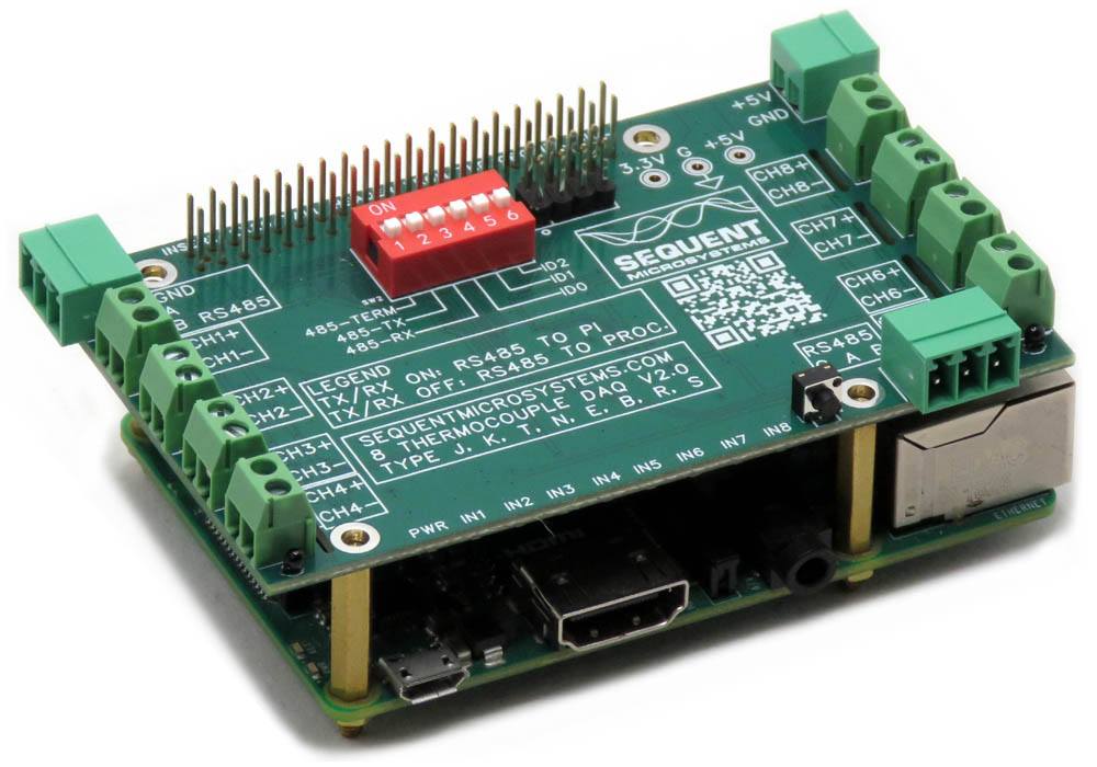


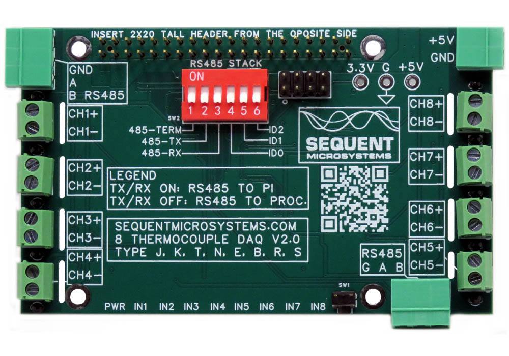

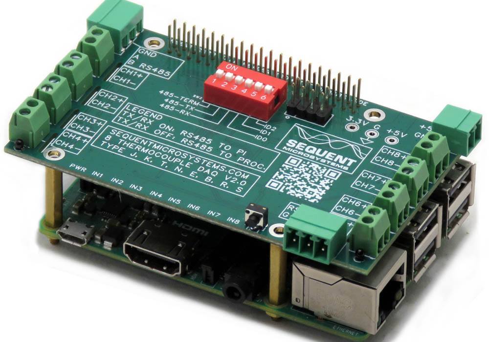


Eight Thermocouples DAQ 8-Layer Stackable HAT for Raspberry Pi
Read eight thermocouples type J, K, T, N, E, B, R and S; 0.1% accuracy through calibration; RS485, Watchdog.
Overview
Compact, stackable temperature data acquisition HAT for Raspberry Pi. Monitors up to eight thermocouple channels per card — 64 when stacked — using high-resolution 24-bit delta-sigma ADCs with automatic cold-junction compensation. Supports J, K, T, N, E, B, R, and S thermocouple types. Includes RS485/MODBUS RTU interface, hardware watchdog, and onboard 5V supply for the Raspberry Pi.
- Eight thermocouple inputs with automatic cold-junction compensation
- Supports J, K, T, N, E, B, R, and S thermocouple types
- 24-bit delta-sigma ADC — ±1% factory accuracy, ±0.01% after calibration
- RS485/MODBUS RTU — operates standalone or under Raspberry Pi control
- Up to 8 cards stackable for 64-channel monitoring
- Uses only I²C — all remaining GPIO pins stay free
Works with Open Automation Software
Compatible with widely used tools for control, monitoring, and system integration.
 |
 |
 |
 |
 |
 |
INTERFACES AND I/O
| I/O's | Communication | Software Integration |
|---|---|---|
| • Eight Thermocouple Inputs (J, K, T, N, E, B, R, S) | • I²C Port to Raspberry Pi | • Command Line |
| • 24-bit Delta-Sigma ADC Resolution | • RS485/MODBUS RTU Port | • Python Library |
| • Automatic Cold-Junction Compensation | • Node-RED nodes | |
| • CODESYS Driver | ||
| • OpenPLC Module | ||
| • Arduino Library | ||
| Other Features | ||
| • User-programmable threshold LEDs for all eight channels | ||
| • Integrated 5V power supply for Raspberry Pi | ||
| • Maximum acquisition rate: 40 samples per second | ||
| • Factory-calibrated accuracy: ±1% — up to ±0.01% after field calibration | • Pluggable connectors for 26–16 AWG field wiring | |
| • PLC-ready via RS485/MODBUS RTU — no Raspberry Pi required | • Onboard hardware watchdog and resettable fuse | |
| • General-purpose programmable pushbutton | • Eight-level stackable — up to 64 thermocouple channels | |
DESCRIPTION
The Eight Thermocouples DAQ HAT provides a compact, high-accuracy solution for monitoring thermocouple sensors directly from Raspberry Pi.
Eight inputs supporting J, K, T, N, E, B, R, and S thermocouple types for industrial and scientific temperature measurement applications.
High-resolution 24-bit delta-sigma A/D converters with ultra-low-drift (0.005 µV/°C), low-offset (50 µV) amplifiers deliver factory accuracy of ±1%, improving to ±0.01% after field calibration.
Automatic cold-junction compensation removes the need for isothermal blocks or manual compensation calculations, simplifying sensor wiring and installation.
Standard RS485 transceiver with IN and OUT ports. Operates as MODBUS RTU slave under Raspberry Pi control or as a standalone device connected directly to a PLC, with no Raspberry Pi required.
Eight user-programmable LEDs illuminate when the corresponding thermocouple channel exceeds a configurable temperature threshold, providing instant visual status at a glance.
The hardware watchdog automatically power-cycles the Raspberry Pi if the software becomes unresponsive, ensuring continuous operation in unattended deployments.
A general-purpose pushbutton routed to GPIO 26 enables safe Raspberry Pi shutdown without requiring a keyboard, monitor, or remote login — essential for headless field deployments.
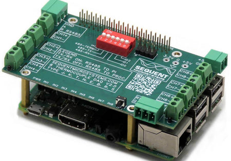
Up to eight cards can be stacked on a single Raspberry Pi, sharing only the I²C bus (two GPIO pins) for monitoring up to 64 thermocouple channels simultaneously.
TECHNICAL DETAILS
CARD LAYOUT

MECHANICAL SPECIFICATIONS

DIP SWITCH AND STACKING
The onboard six-position DIP switch configures both the stack address and the RS485 port behavior. Cards of different Sequent HAT types can be freely mixed in the same stack.
| Switch | Name | Function |
|---|---|---|
| TERM | RS485 termination | Enable on the last card in an RS485 chain to prevent signal reflections |
| TX | RS485 TX select | ON: Raspberry Pi drives RS485 directly |
| RX | RS485 RX select | ON: Raspberry Pi receives RS485 directly |
| ID0 | Stack ID bit 0 | Binary stack address bit 0 (LSB) — sets card level 0–7 |
| ID1 | Stack ID bit 1 | Binary stack address bit 1 |
| ID2 | Stack ID bit 2 | Binary stack address bit 2 (MSB) |
ELECTRICAL SPECIFICATIONS
| Power | |
|---|---|
| Power supply | 5V from Raspberry Pi GPIO bus or pluggable connector |
| Power consumption | 50 mA |
| Onboard resettable fuse | Yes |
| Thermocouple Inputs | |
|---|---|
| Channels | 8 |
| Thermocouple types | J, K, T, N, E, B, R, S |
| ADC resolution | 24-bit delta-sigma |
| Maximum sample rate | 40 SPS |
| Factory accuracy | ±1% |
| Accuracy after calibration | ±0.01% |
| Amplifier drift | 0.005 µV/°C |
| Amplifier offset | 50 µV max |
| Cold-junction compensation | Automatic |
| General | |
|---|---|
| Operating temperature | −40°C to 85°C |
| Wire gauge (connectors) | 26–16 AWG |
POWER REQUIREMENTS
Power supply: The card is powered from the Raspberry Pi GPIO bus (5V) or from its own pluggable 2-pin connector. Operating current is 50 mA. An integrated 5V supply delivers power to the Raspberry Pi when used as a HAT, eliminating the need for a separate Raspberry Pi power supply.
FIELD CALIBRATION
All thermocouple inputs are factory-calibrated. Firmware commands allow the user to recalibrate the board or perform higher-precision calibration if required.
Calibration is performed using a two-point method with an external high-precision voltage reference. The two calibration points should be placed as far apart as possible within the measurement range to maximize accuracy.
Calibration values are stored in non-volatile flash memory. If an incorrect value is entered during calibration, a RESET command can restore factory calibration values and the procedure can be repeated.
For a full list of calibration commands, run: smtc -h
COMMUNICATION INTERFACES
HARDWARE WATCHDOG
The Eight Thermocouples DAQ HAT includes a hardware watchdog that ensures your system automatically recovers if the Raspberry Pi software becomes unresponsive. The watchdog is disabled at power-up and activates after it receives the first reset command from the Raspberry Pi.
| Watchdog Parameters | |
|---|---|
| Initial timeout period | Configurable — allows time for Raspberry Pi to boot and start the application |
| Running timeout period | Configurable — normal operating timeout |
| Off period | Configurable — duration the Raspberry Pi power is cut when timeout triggers |
| Reset counter | Stored in non-volatile flash; can be read or cleared at any time |
For a full list of watchdog commands, run: smtc -h
COMPATIBILITY
| Interface | I²C |
| GPIO used | GPIO2 (SDA), GPIO3 (SCL) — 2 pins only; remaining 24 GPIO pins stay free |
| Max stack | 8 cards — up to 64 thermocouple channels |
| Compatible with | All Raspberry Pi versions from Zero to 5 (40-pin GPIO header) |
FIRMWARE UPDATE
The onboard microcontroller firmware can be updated in the field. The update tool downloads the latest firmware from Sequent Microsystems' servers and flashes it to the board over I²C.
Running the Update
~$ cd ~/smtc-rpi/update/
~/smtc-rpi/update$ ./update <id>
Replace <id> with the board stack address (0–7). Full instructions including recovery procedures are available at:
https://github.com/SequentMicrosystems/smtc-rpi/blob/main/update/README.md
ERRATA
DOWNLOADS
| User's Guide (PDF) | Schematics (PDF) | CAD | Software & Integrations |
|---|---|---|---|
| User's Guide V1.1 | Schematic V1.1 | 3D STEP Model V1.1 | Command Line |
| User's Guide V2 | Schematic V2.0 | 3D Printing Enclosure | Python Library |
| Node-RED nodes | |||
| MODBUS interface | |||
| CODESYS Library | |||
| Arduino Library |
WHAT'S INCLUDED
When you purchase the card you will receive the following items:
| 1. Eight Thermocouples DAQ HAT for Raspberry Pi |
|---|
|
| 2. Mounting Hardware | |
|---|---|
 |
|
| 3. Connector Plugs for all Inputs and Power | |
|---|---|
 |
|
QUICK START
- Plug your card on top of your Raspberry Pi and power up the system.
- Enable I²C communication on Raspberry Pi using
raspi-config. - Install the software from GitHub:
~$ git clone https://github.com/SequentMicrosystems/smtc-rpi.git~$ cd /home/pi/smtc-rpi~/smtc-rpi$ sudo make install~/smtc-rpi$ smtc
The program will respond with a list of available commands. To read more about the CLI, please refer to the README file. If you would rather use a different platform, you can access the same functionality through dedicated, ready-to-use integrations in the Downloads tab above.
Expand Your System
-
 Coming soon
Eight 24-Bit Analog Inputs DAQ 8-Layer Stackable HAT for Raspberry Pi
Eight Differential or Common Ground 24 bit inputs software selectable to ±0.75V, ±1.5V, ±3V, ±6V, ±12V, ±24V with status LEDs; RS485, Watchdog. -
 In stock
Sixteen Relays 2A/24V 8-Layer Stackable HAT for Raspberry Pi
Sixteen relays with status LEDs and Normal Open contacts; RS485 and Hardware Watchdog. -
 In stock
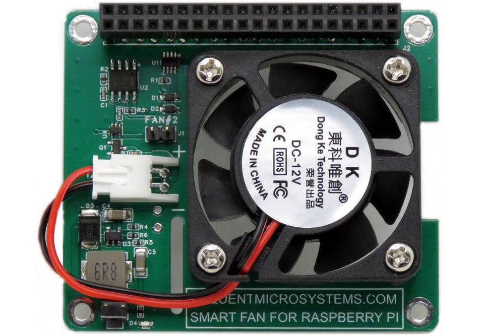
Smart Fan HAT the Best Cooling Solution for Raspberry Pi
PWM controlled 40x40x10mm Fan keeps Raspberry Pi temperature constant; Stackable with any other HAT. -
 In stock
DIN-RAIL Kit Type1 Parallel Mount for Raspberry Pi
Install Raspberry Pi and multiple HATs parallel on the DIN-Rail; 90% rotation; Raspberry Pi 1 to 5.


