
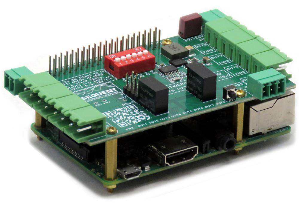


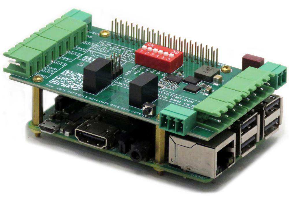


Eight MOSFETS 8-Layer Stackable HAT for Raspberry Pi
Four PWM Loads 12A/24V plus four PWM loads 4A/240V with status LEDs; RS485/MODBUS Port.
The Eight MOSFETS Stackable Card is a high-power switching solution for Raspberry Pi, designed to drive both high-current and high-voltage DC loads. With onboard PWM control, RS485/MODBUS RTU support, and full compatibility with Sequent Microsystems' 8-layer stackable architecture, this card is ideal for industrial automation, lighting, and motor control applications.
FEATURES
The latest version of the card (V6.0) has several major improvements:
-
Onboard processor enables proportional load control via 1 kHz PWM
-
RS485 port connected to local processor allows MODBUS RTU slave operation — compatible with external PLCs, no Raspberry Pi required
-
Heavy-duty 5 mm pluggable connectors support loads up to 12 A
-
High-current channels are galvanically isolated from high-voltage channels
-
TVS diode protection on high-current outputs; diode protection on high-voltage outputs
-
All jumpers replaced with DIP switches for easier configuration
-
Software compatible with previous versions
-
Can be powered from 5 V or 10–24 V DC power supplies
-
Provides regulated 5 V power (up to 5 A) to Raspberry Pi
-
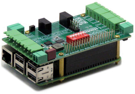
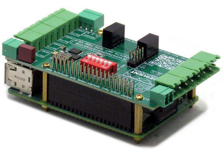
Stackable up to eight layers
-
Compatible with all Raspberry Pi models, from Zero to Pi 5
-
Four high-current outputs: 12 A @ 24 V DC
-
Four high-voltage outputs: 4 A @ 240 V DC
-
PWM control at 1 kHz on all outputs
-
General-purpose/reset pushbutton
-
Status LEDs on all outputs for visual feedback
-
Pluggable connectors support 24–12 AWG wires
-
DIP switch for stack level and RS485 configuration
-
RS485 port with MODBUS RTU protocol support
-
I²C interface only (uses addresses 0x38–0x3F); all GPIO pins remain available
-
ECCN classification: EAR99
-
All mounting hardware included: standoffs, screws, and nuts
-
Open-source hardware; schematics available
DESCRIPTION
The Eight MOSFETS Stackable Card is an industrial-grade output expansion module designed to interface seamlessly with any Raspberry Pi model, from Zero to Pi 5. It features eight powerful MOSFET channels—four high-current (12 A @ 24 V DC) and four high-voltage (4 A @ 240 V DC)—making it ideal for controlling motors, solenoids, industrial relays, and lighting systems.
Each output is driven by an onboard processor capable of generating 1 kHz PWM signals for precise proportional load control. A robust RS485 port, connected to the local processor, allows the board to operate independently of the Raspberry Pi as a MODBUS RTU slave, enabling easy integration with PLCs and industrial controllers.
The board offers galvanic isolation between high-current and high-voltage channels, with built-in TVS and flyback diode protection to safeguard both the board and connected equipment. Configuration is simplified with DIP switches—no jumpers required. Status LEDs provide real-time feedback on all outputs.
The card uses only the I²C interface (selectable addresses 0x20–0x27 or 0x38–0x3F), leaving all Raspberry Pi GPIO pins available. Power can be supplied via a 5 V or 10–24 V DC input, with onboard regulation delivering up to 5 A to the Raspberry Pi. Heavy-duty, pluggable connectors support 24–12 AWG wires for secure field wiring.
Fully compatible with Sequent Microsystems' 8-layer stackable system, this card is engineered for scalability, reliability, and flexibility in industrial automation applications. All required mounting hardware is included, and open-source schematics are available for developers and integrators.
The Eight MOSFETS card offers flexible power input options to suit a wide range of industrial applications. It can be powered in one of two ways:
-
5 V Input: When a stable 5 V power supply is available, the card can be powered directly through the standard 5 V rail. In this mode, the Raspberry Pi and the card share the same 5 V supply.
-
10–24 V DC Input: For industrial environments where 12 V or 24 V power is more common, the card accepts input voltages from 10 V to 24 V. An onboard DC-DC converter regulates this input down to 5 V to power the card and provide up to 5 A of regulated 5 V output to the Raspberry Pi. This eliminates the need for a separate Raspberry Pi power supply.
This dual-input flexibility ensures compatibility with both lab setups and industrial control panels, while simplifying wiring and reducing the number of external power supplies required.
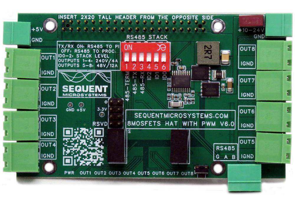
DIP SWITCH CONFIGURATION
A six-position DIP switch is used to configure the RS485 port source and to set the card’s stack position when multiple cards are installed.

STACKING MULTIPLE CARDS
Up to eight cards can be stacked on a single Raspberry Pi. Three positions of the configuration DIP switch—labeled ID0, ID1, and ID2—are used to set the stack level for each card. Cards can be installed in any order, as long as each one has a unique ID setting.
RS485/MODBUS PORT
The card features an RS485 port that can be driven either by the Raspberry Pi or by the onboard local processor. The selection is controlled using two DIP switch positions labeled TX and RX.
-
DIP Switches OFF (default):
The RS485 port is connected to the local processor. In this mode, the card functions as a MODBUS RTU slave, allowing any MODBUS master to read all inputs and set all outputs using standard MODBUS commands. A complete list of supported commands and register addresses is available on the project's GitHub repository. -
DIP Switches ON:
The RS485 port is connected to USART1 of the Raspberry Pi, and the card acts as a passive hardware bridge. In this mode, the Raspberry Pi can communicate with any external RS485 device, but the card itself does not interpret or respond to MODBUS commands. It only provides RS485-level signal conversion.Before using this mode, you must instruct the local processor to release control of the RS485 bus using the following command:
In both configurations, the RS485 data direction is managed by the local processor. Control of the RS485 TX enable signal depends on whether jumpers are installed or removed:
-
Jumpers Installed: RS485 control is handed over to the local processor (for MODBUS slave mode).
-
Jumpers Removed: RS485 TX/RX is fully controlled by the Raspberry Pi (for external MODBUS master communication).
Refer to the command-line utility help for more details on configuring RS485 behavior.
RS485 TERMINATOR
The last position on the DIP switch controls the RS485 line termination. Set it to ON if the card is the last device on the RS485 bus.
Improperly shutting down the Raspberry Pi by cutting power directly can lead to SD card corruption. To avoid this, a safe shutdown command should be issued before powering off. However, doing so typically requires a monitor, keyboard, and mouse connected to the Pi.
To simplify this process, a momentary pushbutton is provided at the edge of the card. This button is connected to pin 37 (GPIO26) and offers a convenient way to initiate a safe shutdown.
To use it, you'll need to write a script that monitors GPIO26. When the button is pressed and held for a predefined duration (e.g., 2–3 seconds), the script should issue a proper shutdown command to the operating system.

- Power supply: 5V/5A or 10V-24V 2.5A
- Power consumption: 10mA
- On board fuse: 2.5A
- MOSFETS 1-4: 250V, 200 mΩ at 10V, 15A
- MOSFETS 5-8: 24V, 4.6 mΩ at 10V, 20A
-
Connector ratings: 300V/15A

APPLICATION: USING THE 8-MOSFET HAT TO DRIVE DC MOTORS

DC Motors from 5V up to 240V, and up to 8A can be driven by using this HAT in combination with the 4-RELAYS 4-INPUTS HAT ( for motors up to 240V DC) or the 8-RELAY HAT for motors up to 120V DC.
DOWNLOADS
RoHS and REACH Compliance Declaration
SOFTWARE
YOUR KIT

- Four M2.5x18mm male-female brass standoffs
- Four M2.5x5mm brass screws
- Four M2.5 brass nuts


QUICK START
- Plug your card on top of your Raspberry Pi and power up the system using only one 5V/3A power supply.
- Enable I2C communication on Raspberry Pi using raspi-config.
- Install the 8-MOSFETS software from github.com:
- ~$ git clone https://github.com/SequentMicrosystems/8mosind-rpi.git
- ~$ cd /home/pi/8mosind-rpi
- ~/8mosind-rpi$ sudo make install
- ~/8mosind-rpi$ 8mosind -h

FAQ
Q: What types of loads can the card control?
A: The card can control both high-current DC loads (up to 12 A @ 24 V) and high-voltage DC loads (up to 4 A @ 240 V), such as motors, solenoids, industrial relays, lighting systems, and resistive or inductive loads.
Q: What Raspberry Pi models are supported?
A: The card is compatible with all Raspberry Pi models featuring a 40-pin GPIO header, including Raspberry Pi Zero, 3, 4, and 5.
Q: Can multiple cards be stacked?
A: Yes, up to eight cards can be stacked on a single Raspberry Pi using DIP switch settings to assign a unique ID to each card.
Q: How are the stack levels configured?
A: Three DIP switch positions labeled ID0, ID1, and ID2 are used to assign each card a unique stack level. Cards can be installed in any order.
Q: What is the purpose of the RS485 port?
A: The RS485 port can be driven either by the local processor (MODBUS RTU slave mode) or by the Raspberry Pi (RS485 master interface). DIP switches select the signal source.
Q: Can the card operate without a Raspberry Pi?
A: Yes. In MODBUS RTU mode, the onboard processor handles communication, allowing the card to be controlled by any MODBUS-compatible PLC or industrial controller.
Q: How do I safely shut down the Raspberry Pi?
A: A reset/shutdown pushbutton is provided and connected to GPIO26 (pin 37). With a simple monitoring script, this button can trigger a safe shutdown when held.
Q: How is power supplied to the card and Raspberry Pi?
A: The card can be powered by either 5 V or 10–24 V DC. It includes an onboard regulator that provides up to 5 A of 5 V output to power the Raspberry Pi.
Q: Is there short-circuit or overcurrent protection?
A: Yes. The board includes a 2.5 A onboard fuse and TVS/diode protection on high-current and high-voltage outputs.
Q: Are jumpers required for configuration?
A: No. All settings are configured via DIP switches, simplifying setup and reducing error.
Q: Is the card open-source?
A: Yes. Schematics and documentation are open source and available on Sequent Microsystems' GitHub repository.
Q: How can I test the card before installation?
A: A built-in self-test mode can be initiated via a command-line utility. The test cycles all MOSFET outputs and confirms functionality through LED indicators
Related products
-
 In stock
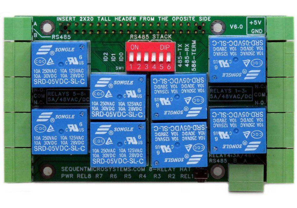
Eight Relays 4A/120V 8-Layer Stackable HAT for Raspberry Pi
Eight Relays 4A/120VAC, 24VDC N.O./N.C. contacts and LED indicators; RS485 Port. -
 In stock
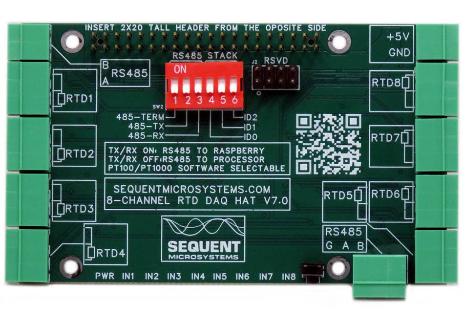
RTD Data Acquisition 8-Layer Stackable HAT for Raspberry Pi
Eight Channel RTD Data Aquisition HAT; 0.01% accuracy through calibration; PT100/1000 Sensors; RS485/MODBUS, Watchdog. -
 In stock
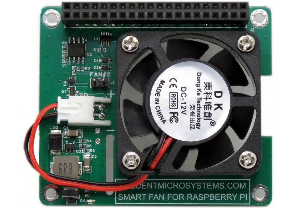
Smart Fan HAT the Best Cooling Solution for Raspberry Pi
PWM controlled 40x40x10mm Fan keeps Raspberry Pi temperature constant; Stackable with any other HAT. -
 In stock
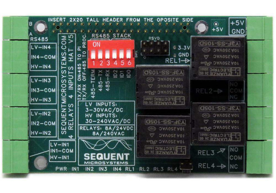
Four Relays four HV Inputs 8-Layer Stackable HAT for Raspberry Pi
Four Relays 8A/240VAC; Four opto-isolated Inputs 3V-240V; RS485/MODBUS; Quadrature encoder, PPS counters, PWM inputs;


