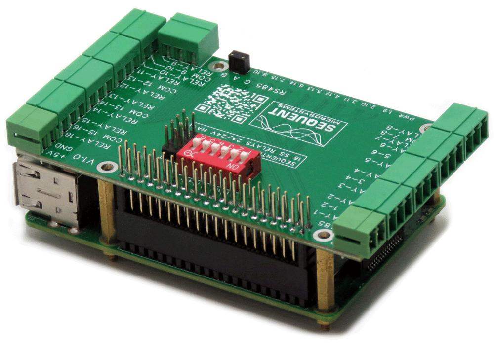

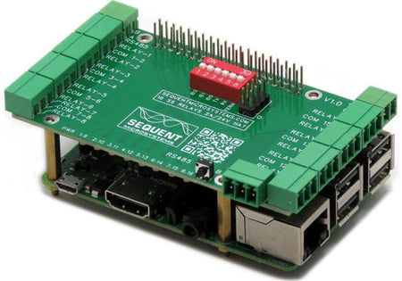

Sixteen Solid State Relays 2A/24V 8-Layer Stackable HAT for Raspberry Pi
Sixteen Solid State relays with status LEDs and Normal Open contacts; RS485/MODBUS; Hardware Watchdog.
FEATURES
- All Relays with Status LEDs and N.O. contacts
- Eight layer stackable to 128 Relays
- Pluggable Connectors 26-16 AWG wires
- 5V power supply with reverse polarity protection
- On board hardware watchdog
- RS485 Port
- General purpose push-button
- 8 LEDs showing status of groups of 8 relays
- Software self-test
- Uses only I2C port, all GPIO pins available
- Works with any Raspberry Pi from ZERO to 5
- ECCN Code EAR99
- Command Line
- Python Library
- Node-Red nodes
- CODESYS Driver
- OpenPLC module
- Home Assistant Integration
- Arduino Library
DESCRIPTION
Copycat of our 16-RELAYS HAT, with one significant difference: Solid State instead of mechanical relays. While mechanical relays are very reliable and have close to zero ohms resistance on contacts, they have a limitation in the number of lifetime cycles.
The relays we use on the 16-RELAY HAT have a Mechanical Life of 1,000,000 operations. While this might be OK if relays are not triggered too often, what if your application requires 1 second intervals? A relay might engage 3,600 times an hour, or 86.400 times each day. It will run out of cycles in less than 2 weeks, which is clearly a major drawback.
This HAT overcomes this limitation, having an infinite number of lifetime cycles.
The Sixteen Solid State Relays Card is software compatible with the Sixteen Relays HAT and can be stacked up to 8 levels in combination with all other Sequent Microsystems cards equipped with a processor.
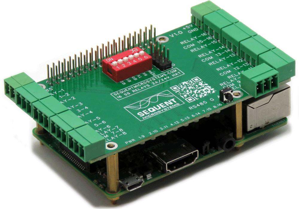
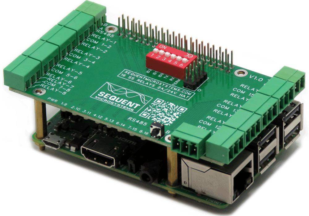
Perfect add-on to your project when you have to control large number of loads. Stackable to 8 layers, the card can add up to 128 relays to each Raspberry Pi in a compact form factor.
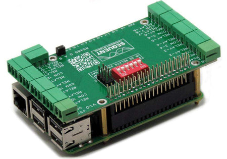
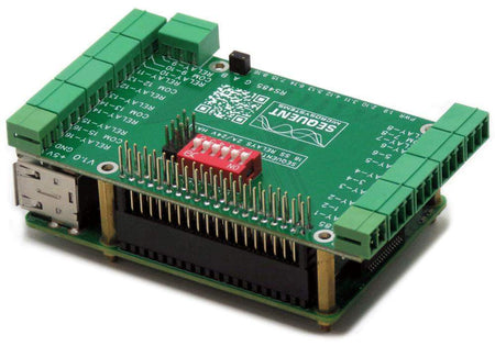
Pluggable connectors make the card easy to use when multiple cards are stacked up.
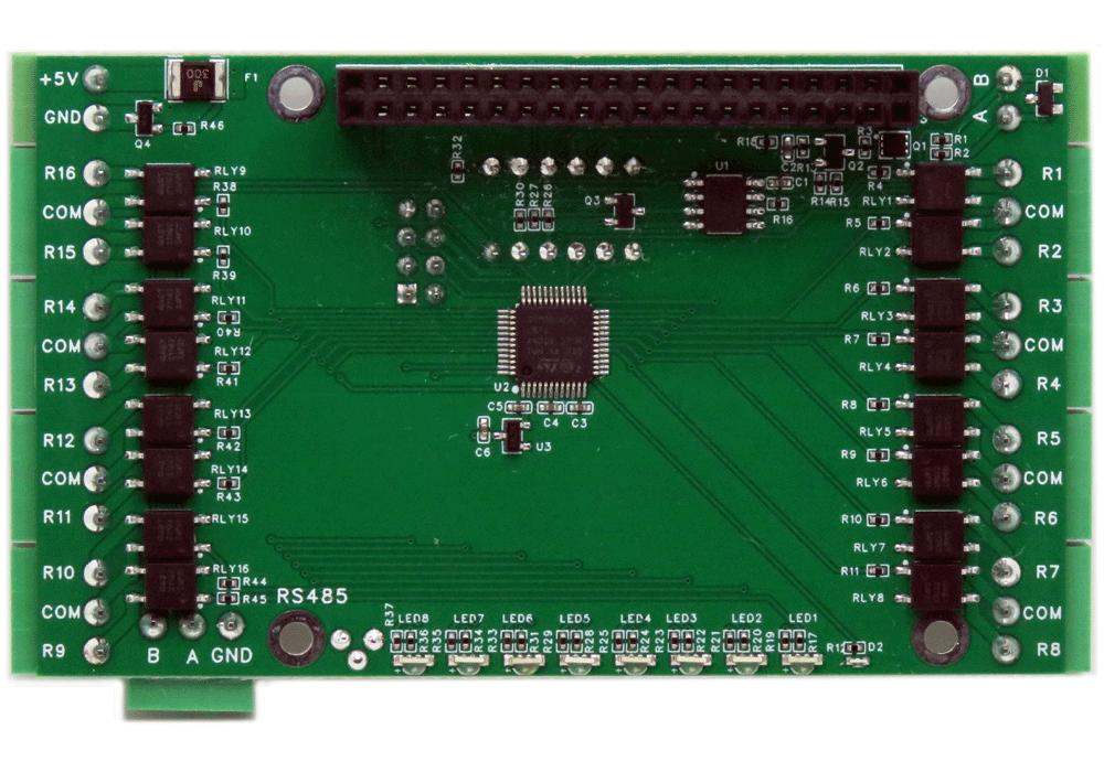
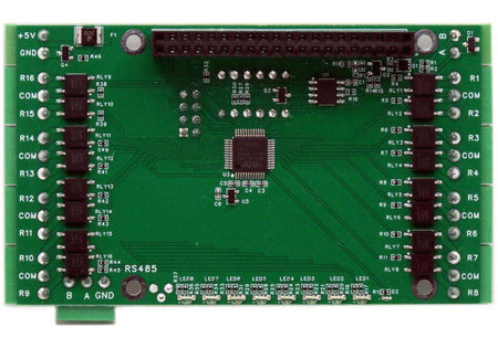
Bicolor LEDs conveniently grouped on one side of the board show when relays are on or off. A power LED shows when power is applied. A reset switch permits shutting down the Raspberry Pi without the use of a keyboard and monitor.
COMPATIBILITY
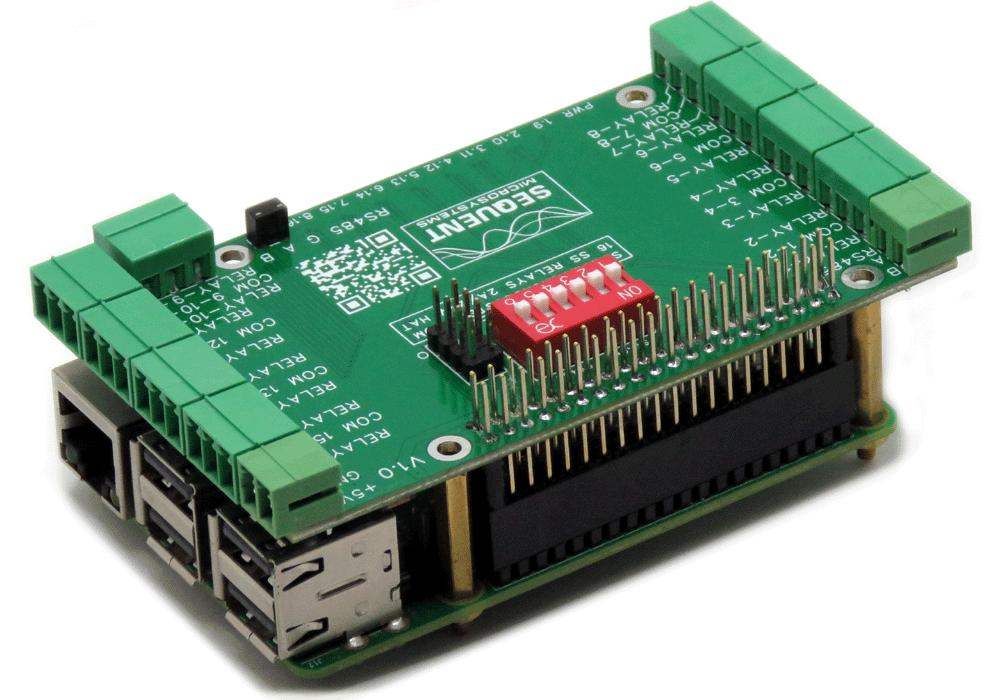
The Sixteen Solid State Relays Card is compatible with all Raspberry Pi versions from Zero to 5. All stacked cards share the I2C bus using only two of the Raspberry Pi’s GPIO pins to manage all eight cards. This feature leaves the remaining 24 GPIOs available for the user.
POWER REQUIREMENTS
The Sixteen Solid State Relays Card needs 5V to operate and can be powered from Raspberry Pi or from it's own 2 pin pluggable connector. The card draws 20mA. If power is applied to the board's connector, no other power supply is needed for the Raspberry Pi.
LED INDICATORS
A power LED shows when power is applied to the board. Due to space limitations, bicolor LEDs are used to shows the status of groups of 8 relays.
DIP SWITCH CONFIGURATION
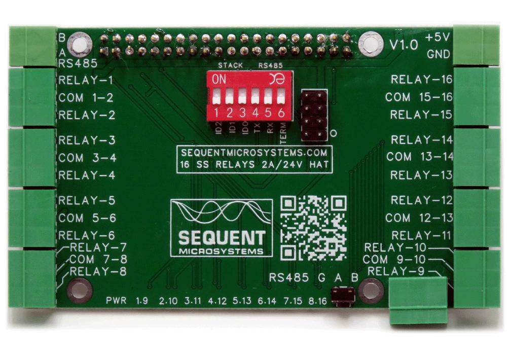
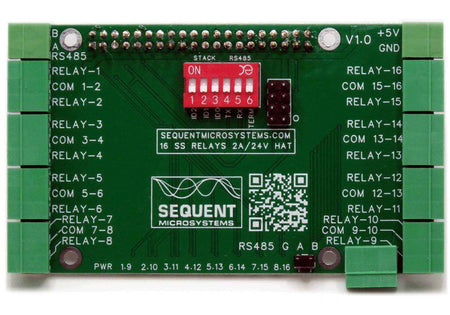
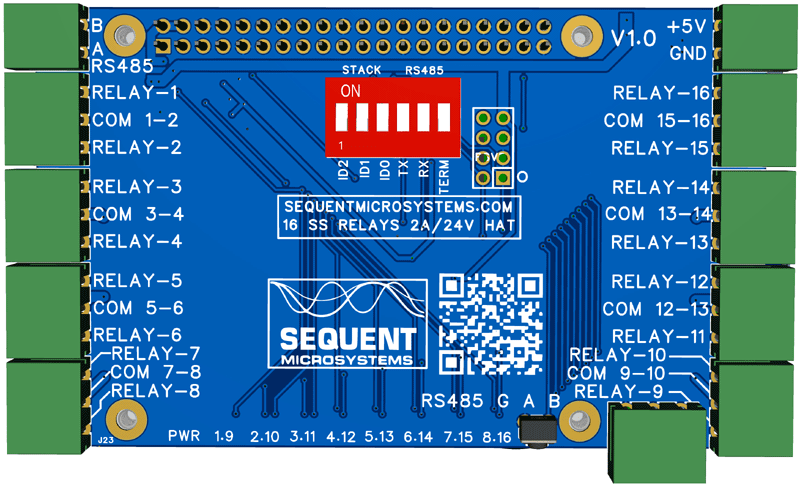
A six position DIP switch is used to select the source of the RS485 port and the position of the card in the stack, if multiple cards are used.

STACKING MULTIPLE CARDS
Up to eight Sixteen Solid State Relays Cards can be stacked on your Raspberry Pi. Three positions of the configuration DIP Switch labeled ID0, ID1, ID2 are used to select the stack level. Cards can be stacked in any order.
RS485/MODBUS PORT
The Sixteen Solid State Relay Card has an RS485 port which can be driven from the Raspberry Pi, or from the local processor. Leave the TX and RX switches in the OFF position to connect the port to the local processor. Set both to ON to connect to USART1 of the Raspberry Pi.
When DIP Switches are ON, Raspberry Pi can communicate with any device with an RS485 interface. In this configuration the card is a passive bridge which implements only the hardware levels required by the RS485 protocol. To use this configuration, you need to tell the local processor to release control of the RS485 bus:
~$ 16relind [0] rs485wr 0 0 0 0 0
When DIP Switches are OFF, the card operates as MODBUS slave and implements the MODBUS RTU protocol. Any MODBUS master can access all the card's inputs, and set all the outputs using standard MODBUS commands. A detailed list of commands implemented and parameters addresses can be found on GitHub:
In both configurations the local processor needs to be programmed to release (jumpers installed) or control (jumpers removed) the RS485 signals. See the command line online help for further information.
RS485 TERMINATOR
The last position on the DIP switch is the RS485 line terminator. Set it to ON if the card is last on the RS485 chain.
REVERSE POWER SUPPLY PROTECTION
The board is protected to accidental reverse power supply with a 5.8A, 39 mOhm MOSFET which breaks the ground line if reverse power is applied.
RESET PUSHBUTTON
Shutting down the Raspberry Pi by turning off the power can result in SD Card failure. To prevent this, a shutdown command needs to be used before power cut-off. But this requires a monitor, keyboard and mouse connected to the Pi.
A momentary on push button installed at the edge of the board provides a convenient way to shut down the Raspberry Pi. The button is routed to pin 37 (GPIO 26). You need to write a script which monitors this pin, and if pressed for more than a desired time, issues the shut-down command.
HARDWARE WATCHDOG
The card contains a built-in hardware watchdog which will guarantee that your mission-critical project will recover and continue running even if Raspberry Pi software hangs up. After power up the watchdog is disabled, and becomes active after it receives the first reset or first period set.
The default timeout is 120 seconds. Once activated, if it does not receive a subsequent reset from Raspberry Pi within 2 minutes, the watchdog cuts the power and restores it after 10 seconds.
Raspberry Pi needs to issue a reset command on the I2C port before the timer on the watchdog expires. The timer period after power up and the active timer period can be set from the command line. The number of resets is stored in flash and can be accessed or cleared from the command line. All the watchdog commands are described by the online help function.
CARD LAYOUT
 ELECTRICAL SPECIFICATIONS
- Power Supply: 5V/8A pluggable connector with reverse polarity protection
- On board resettable fuse: 3A
- Relays: NO contacts, 2.0A/24 VAC/DC
- Ron resistance: 60mΩ typ.
- Off state leakage current: max. 1μA
- Turn On Time: 1.5mS max.
- Turn Off Time: 0.5mS max.
- Load Current: 2.5A max.
- Peak Load Current: 5A 100mS pulse
- Electrical and Mechanical endurance: unlimited
MECHANICAL SPECIFICATIONS

DOWNLOADS
RoHS and REACH Compliance Declaration
SOFTWARE
SOFTWARE INTERFACES
You can write your own application using the Command Line or Python Libraries provided. No programming is required if you use the Node-Red nodes we supply. You can drag-and-drop the functional blocks to design your application. Examples are provided at GitHub.
RELAY SELF TEST
The card can be tested before installation by running a simple command from the command line. The card will cycle each relay on and off at 0.5 seconds interval. The lighting of the LEDs will assure that all relays are functioning.
ACCESSORIES
DIN-RAIL MOUNTING
The 16-Relays Card can be installed parallel on a DIN-Rail using the DIN-Rail Kit Type 1, or perpendicular using the DIN-Rail Kit Type 2.
YOUR KIT
When you purchase the 16-Relays Card you will receive the following items:
1. Sixteen Solid State Relays for Raspberry Pi

2. Mounting hardware
- Four M2.5x18mm male-female brass standoffs
- Four M2.5x5mm brass screws
- Four M2.5 brass nuts


QUICK START
- Plug your Solid State Relays Card on top of your Raspberry Pi and power up the system.
- Enable I2C communication on Raspberry Pi using raspi-config.
- Install the 16-RELAYS software from github.com:
-
- ~$ git clone https://github.com/SequentMicrosystems/16relind-rpi.git
- ~$ cd /home/pi/16relind-rpi
- ~/16relind-rpi$ sudo make install
- ~/16relind-rpi$ 16relind
The program will respond with a list of available commands.
Related products
-
 In stock
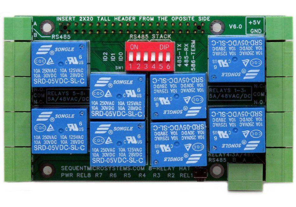
Eight Relays 4A/120V 8-Layer Stackable HAT for Raspberry Pi
Eight Relays 4A/120VAC, 24VDC N.O./N.C. contacts and LED indicators; RS485 Port. -
 In stock
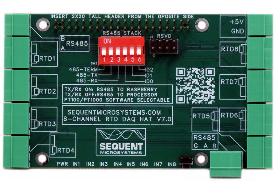
RTD Data Acquisition 8-Layer Stackable HAT for Raspberry Pi
Eight Channel RTD Data Aquisition HAT; 0.01% accuracy through calibration; PT100/1000 Sensors; RS485/MODBUS, Watchdog. -
 In stock
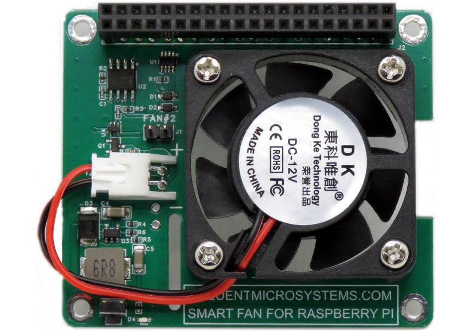
Smart Fan HAT the Best Cooling Solution for Raspberry Pi
PWM controlled 40x40x10mm Fan keeps Raspberry Pi temperature constant; Stackable with any other HAT. -
 In stock
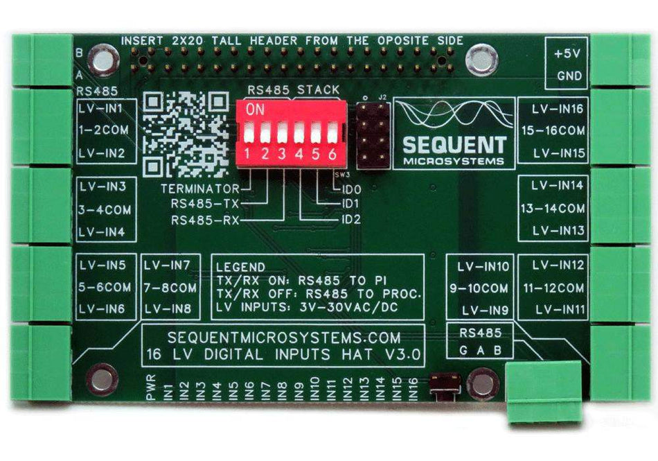
Sixteen LV Digital Inputs 8-Layer Stackable HAT for Raspberry Pi
Sixteen 3V-48V Opto-isolated Inputs with LED indicators; RS485/MODBUS, Hardware Watchdog.


